Annals of Robotics and Automation
Digital twinning of surveillance robot
Saranya M1*, Archana N2, Lavanya SS3, Ooviyavalli K4, Sneha B5 and Sujana K6
2Assistant Professor (Sl. Gr.), Department of EEE, PSG College of Technology, Coimbatore, India
3UG Students, Department of I&CE, PSG College of Technology, Coimbatore, India
Cite this as
Saranya M, Archana N, Lavanya SS, Ooviyavalli K, Sneha B, et al. (2024) Digital twinning of surveillance robot. Ann Robot Automation 8(1): 001-007. DOI: 10.17352/ara.000017Copyright
© 2024 Saranya M, et al. This is an open-access article distributed under the terms of the Creative Commons Attribution License, which permits unrestricted use, distribution, and reproduction in any medium, provided the original author and source are credited.Surveillance robots provide troops with real-time information about their surroundings, including enemy positions, terrain, and potential threats. This information is invaluable for making informed decisions and ensuring the safety of military personnel. Geo-fenced robots are robots equipped with technology that restricts their movements within predefined geographic boundaries. These boundaries are typically established using GPS or other location-based technologies. In applications like the military, geo-fencing can be used to establish secure zones. Geo-fencing helps prevent robots from entering hazardous areas, reducing the risk of damage to the robot and potential harm to friendly forces or civilians This project aims at Digital twinning of robots by creating a virtual replica or model of a physical robot in a digital environment. Digital twinning allows engineers and designers to simulate and test the robot’s behavior, performance, and capabilities in a virtual environment before building the physical robot. This can lead to increased efficiency, reduced downtime, and cost savings. In this project, LiDAR (Light Detection and Ranging) sensor data is integrated with a digital twinned robot to create a virtual reproduction of the robot and its surroundings. LiDAR is a remote sensing technology that maps the robot’s surroundings in fine detail using 3D point clouds by measuring distances using laser pulses. Here we make use of RPLIDAR A1 M8 and acquire data from it using ROS with the help of a RaspberryPi4B Controller. Simulink is used to create a 3D model of the robot’s environment and the robot itself. Reinforcement learning and pure pursuit algorithms are used for developing them. This project discusses the need for geofenced autonomous robots and emphasizes the security and reliability it brings to military applications.
Introduction
In military applications, geofenced robots can be deployed along the perimeter of military bases and installations to enhance security. By restricting their operations to defined boundaries, these robots can autonomously patrol the area, detect intruders, and respond to security breaches. Non-geofenced robots may pose security risks if they can access sensitive or restricted areas. Unauthorized access to critical infrastructure or classified zones could be a significant concern. Managing and controlling non-geofenced robots can be more complex, as their movements are less predictable. This complexity may require more sophisticated planning and monitoring. In environments where there are potential safety hazards or risks, non-geofenced robots may require more robust safety mechanisms and fail-safes to prevent accidents. This project is aimed at developing a compact robot that can guard a designated Area. To stay within an area, security personnel use mapping software to create a geo-fenced perimeter [1]. The robot then moves and detects objects using a Light Detection and Ranging (LIDAR) sensor, which emits a laser in a 360-degree sweep every 25 milliseconds around the robot. This creates a point cloud, such as a 3-D image of the surroundings showing the objects within the geo-fenced area. Unlike the GPS in your smartphone, which finds locations within a few meters from you, this robot uses a differential GPS that finds objects within a few centimeters. That helps the robot know exactly where it’s moving at all times. It makes use of the scan and pose data from LIDAR to serve the purpose. Digital twinning allows real-time monitoring of the robot’s physical environment through a virtual model [2,3]. Security personnel can remotely control the robot and receive live data. This enables them to respond to security incidents or conduct surveillance from a central location. The digital twinned robot is given with the occupancy grid which serves as its geofenced area. The location of the existing geographic structure that the robot might consider as an obstacle is also given in the occupancy grid. Thus, if there exists an obstacle other than these, then the robot takes an alternate path to move toward the target.
Related works
A literature survey is the most important step in a project development process. Before developing the tool, it is necessary to determine the time factor, economy, and company’s strength. Once these things are satisfied, then the next steps are to determine which operation system and hardware components are needed for the development of the project. Before developing the project, the people need external support. This external support can be taken from books or websites.
A. Ramesh, in a paper published in 2013 [4], described an autonomous robot as a machine able to extract information from its environment and use knowledge about its world to move safely in a meaningful and purposive manner. The trajectory tracking task in non-holonomic systems can be performed through differentiable control laws. The most important feature of this work is that the complete modelling and control are done in SIMSCAPE software which employs a physical network approach that differs from the standard SIMULINK modelling approach and is particularly suited to simulate systems that consist of real physical components. Thus, modelling is done with MATLAB- SIMSCAPE in which physical units for parameters and variables and all unit conversions are handled automatically.
M. B. Emara, A. W. Youssef, M. Mashaly, J. Kiefer, L. A. Shihata, and E. Azab, in the paper published in Jan. 2022 [5], briefed about a digital model for a three-wheeled omnidirectional robot is created. This robot can potentially be used in various industrial applications as it can move quickly in any direction from any configuration. A simulation program - SIMSCAPE a MATLAB-based library - is used for creating a digital twin model for the robot. A hardware prototype is manufactured and a PID controller is used to measure and validate the performance of the proposed digital model. Digital twined models are created using real-time simulation software, in which multiple aspects are studied regarding the system’s control and modelling to ensure that the implementation of the robot in real life is as cost-efficient and error-free as can it be.
Luigi Girletti; Milan Groshev; Carlos Guimarães; Carlos J. Bernardos Universidad Carlos III de Madrid, Antonio de la
Oliva in the paper published in Mar. 2021 [6] had Digital Twin as one of the use cases targeted by the fourth industrial revolution (Industry 4.0), which, through the digitalization of the robotic systems, will enable enhanced automation and remote controlling capabilities. Building upon this concept, this work proposes a solution for an Edge-based Digital Twin for robotics, which leverages the cloud-to-things continuum to offload computation and intelligence from the robots to the network. This imposes stringent requirements over the communication technologies which are fulfilled by relying on 5G.
Methodology
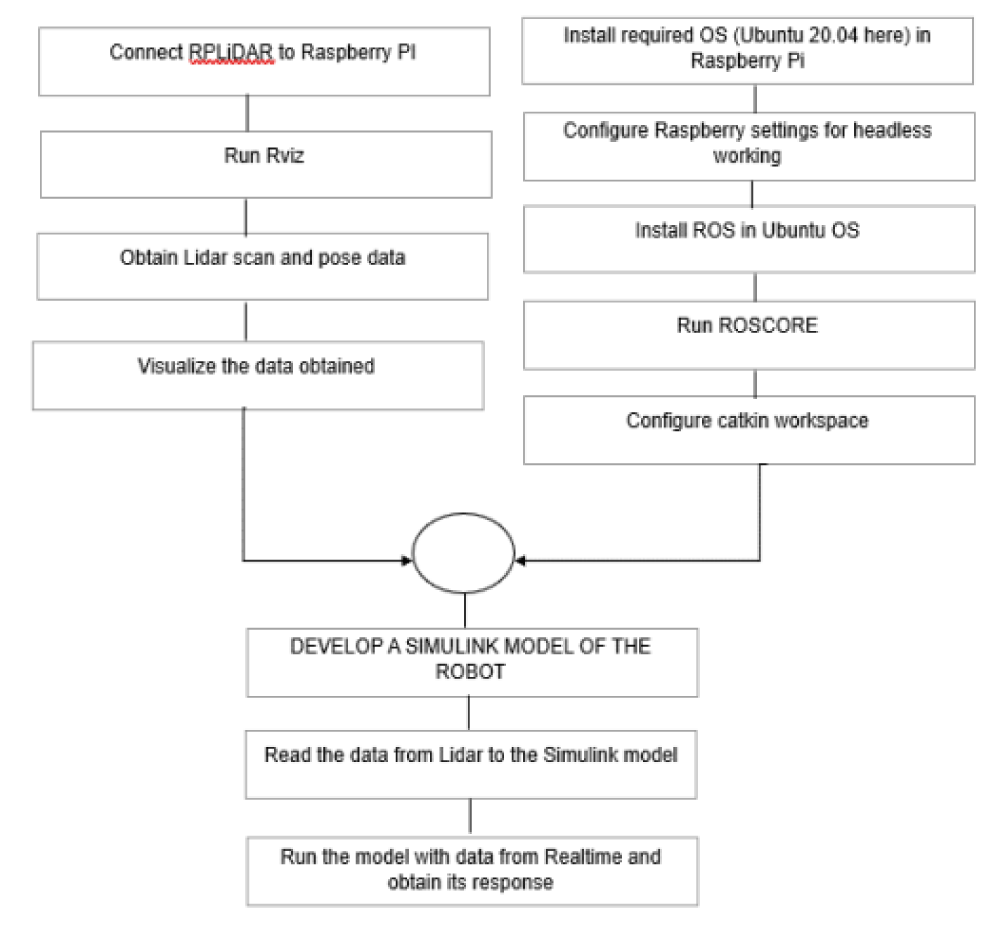
ROS provides the infrastructure and tools needed to create and manage digital twins, especially in the context of robotic and autonomous systems, where sensor data, control, and communication are key components of the twin’s functionality [7]. ROS packages and updates are primarily designed and tested for Ubuntu. ‘roscore’ will provide the central communication and naming services needed for your ROS nodes to interact with each other. A Catkin workspace is a directory structure where you organize and manage your ROS packages. All these are configured and all the required packages and tools are installed. Then if the LIDAR sensor requires specific drivers, you’ll need to configure and launch them. Create a launch file that launches your LIDAR node and any other nodes required for your application [8,9]. Launch RViz and configure it to visualize the LIDAR data. Open Simulink, create a new model and save it. Configure the simulation parameters, such as the simulation time, solver settings, and stop time. Once the simulation is complete, you can observe and analyse the response in the visualization blocks you added. This flow is described in the Figure 1.
As mentioned in the methodology here two laptops are used. One for the master in which ‘roscore’ runs (one on the left side) and the other one in which the Simulink model is developed and receives data from the master. The Lidar (RP Lidar A1 M8) is connected to the Raspberry Pi controller. This Lidar is the one that publishes the required data.
Implementation
Digital twinning is a technology that involves creating a virtual, digital replica or representation of a physical object, system, or environment. Software plays a crucial role in the implementation of digital twinning, as it is responsible for modeling, simulating, and connecting the digital twin to its physical counterpart. For digital twins of systems with control systems, simulators like MATLAB/Simulink are used to model and simulate the control algorithms and their interactions with the physical system [10].
Software implementation
- Developing a simulink model: This example uses a model that implements a post-obstacle avoidance path controller. The controller receives robot position and laser scanning data from the simulated robot and sends velocity commands to guide the robot along a specific path. You can adjust parameters while the model is running and observe the effect on the simulated robot. The model is divided into four subsystems. The following sections explain each subsystem [11].
- ROS in Raspberry Pi: Robot Operating System (ROS) is a commonly used framework for designing complex robotic systems. It is popular for building distributed robot software systems, as well as for its integration with packages for simulation, visualization, robotics algorithms, and more. ROS has become increasingly popular in industry as well, especially in the development of autonomous vehicles [12,13]. ROS + Raspberry Pi is such a powerful combination to create smart robots, with a somehow low cost, and very small electronic board embedded in the robot. The “default” operating system for Raspberry Pi is Raspbian. However, if you want to use ROS, you’d be better served by using an Ubuntu version for the Pi. Installing ROS packages and managing them on Raspbian can be quite difficult, whereas on Ubuntu it’ll work almost out of the box, just like on a standard computer or laptop.
- ROS Network: A Robot Operating System (ROS) is a communication interface that enables different parts of a robot system to discover each other, and send and receive data between them [14]. MATLAB® supports ROS with a library of functions that enables you to exchange data with ROS-enabled physical robots or robot simulators. ROS Toolbox provides an interface connecting MATLAB and Simulink with the Robot Operating System (ROS and ROS 2). With the toolbox, you can design a network of ROS nodes and combine MATLAB or Simulink-generated ROS nodes with your existing ROS network [15]. The toolbox includes MATLAB functions and Simulink blocks to visualize and analyze ROS data by recording, importing, and playing back rosbag files. The toolbox lets you verify ROS nodes via desktop simulation and by connecting to external robot simulators. Use the ROS Logger app to record ROS messages during Simulink® simulation, and obtain a rosbag file with fully synchronized ROS messages saved during simulation [16-18].
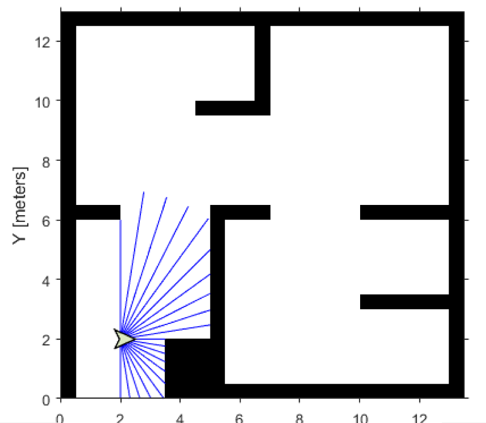
- HECTOR SLAM package: hector_mapping is a SLAM approach that can be used without odometry as well as on platforms that exhibit roll/pitch motion. It leverages the high update rate of modern LIDAR systems. To use hector_mapping, you need a source of sensor_msgs/LaserScan data. The node uses tf for the transformation of scan data, so the LIDAR does not have to be fixed related to the specified base frame [19]. hector_mapping is a node for LIDAR-based SLAM with no odometry and low computational resources. LIDAR scan data may include information about the angular resolution, which determines how densely measurements are taken within the sensor’s field of view. The higher angular resolution provides more detailed data. The number of individual measurements or scan points in a LIDAR scan depends on the LIDAR sensor’s characteristics and settings Figure 2.
Process inputs: The ‘Inputs’ subsystem processes all the inputs to the algorithm. There are two subscribers to receive data from the simulator. The first subscriber receives messages sent on the /scan topic. The laser scan message is then processed to extract scan ranges and angles. The second subscriber receives messages sent on the /ground_truth_pose topic. The (x,y) location and Yaw orientation of the robot are then extracted from the pose message.
Compute Velocity and Heading for Path Following: The ‘Compute Velocity and Heading for Path Following’ subsystem computes the linear and angular velocity commands and the target moving direction using the Pure Pursuit block. The pure pursuit algorithm was originally devised as a method for calculating the arc necessary to get a robot back onto a path. Pure pursuit is a tracking algorithm that works by calculating the curvature that will move a vehicle from its current position to some goal position. The whole point of the algorithm is to choose a goal position that is some distance ahead of the vehicle on the path.
Adjust Velocities to Avoid Obstacles: The ‘Adjust Velocities to Avoid Obstacles’ subsystem computes adjustments to the linear and angular velocities computed by the path follower. The Vector Field Histogram block uses the laser range readings to check if the target direction computed using the Pure Pursuit block is obstacle-free or not based on the laser scan data. If there are obstacles along the target direction, the Vector Field Histogram block computes a steering direction that is closest to the target direction and is obstacle-free. The Vector Field Histogram block is also located in the Mobile Robot Algorithms sub-library. The steering direction is NaN value when there are no obstacle-free directions in the sensor field of view. In this case, a recovery motion is required, where the robot turns on the spot until an obstacle-free direction is available. Based on the steering direction, this subsystem computes adjustments in linear and angular velocities.
Send Velocity Commands: The ‘Outputs’ subsystem publishes the linear and angular velocities to drive the simulated robot. It adds the velocities computed using the Pure Pursuit path following the algorithm with the adjustments computed. The final velocities are set on the geometry_msgs/Twist message and published on the topic /mobile_base/commands/velocity. This is an enabled subsystem that is triggered when a new laser message is received. This means a velocity command is published only when new sensor information is available. This prevents the robot from hitting obstacles in case of a delay in receiving sensor information.
Hardware implementation
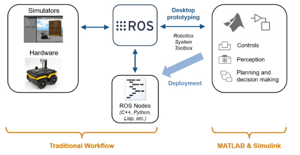
In this project, the acquisition and processing of LiDAR data were enabled by ROS (Robot Operating System) on a Raspberry Pi, with seamless integration into MATLAB. The hardware plays a crucial role in connecting the digital twin to its physical counterpart, collecting data from sensors, and controlling the physical system. This innovative hardware-software synergy allowed for the collection of precise LiDAR data and the utilization of MATLAB’s analytical capabilities for advanced data analysis. The ROS-MATLAB interface is a useful interface for robot algorithms in MATLAB and testing it on ROS-compatible robots. The robotics system toolbox in MATLAB provides the interface between MATLAB and ROS. We can prototype our algorithm and test it on a ROS-enabled robot or in robot simulators such as Gazebo. From MATLAB, we can publish or subscribe to a topic, such as a ROS node, and we can make it a ROS master. The MATLAB-ROS interface has most of the ROS functionalities that we need. From the preceding figure, you can understand, that MATLAB is equipped with powerful toolboxes such as computer vision, control system, and signal processing. We can fetch the data from the robot through the ROS interface and process using this toolbox. After processing sensor data, we can also send control commands to the robot.
- Raspberry PI 4B: Raspberry Pi 4 Model B is the latest product in the popular Raspberry Pi range of computers [18]. It offers a ground-breaking increase in processor speed, multimedia performance, memory, and connectivity compared to the prior-generation Raspberry Pi 4 Model B+ while retaining backward compatibility and similar power consumption. For the end user, Raspberry Pi 4 Model B provides desktop performance comparable to entry-level x86 PC systems. This product’s key features include a high-performance 64-bit quad-core processor, dual-display support at resolutions up to 4K via a pair of micro-HDMI ports, hardware video decodes at up to 4Kp60, up to 4GB of RAM, dual-band 2.4/5.0 GHz wireless LAN, Bluetooth 5.0, Gigabit Ethernet, USB 3.0, and PoE capability (via a separate PoE HAT add-on). The dual-band wireless LAN and Bluetooth have modular compliance certification, allowing the board to be designed into end products with significantly reduced compliance testing, improving both cost and time to market. The Pi4B requires a good quality USB-C power supply capable of delivering 5V at 3A. If attached downstream USB devices consume less than 500mA, a 5V, 3.5A supply may be used.
- RPLIDAR A1M8: RPLIDAR A1 is a low-cost 260-degree 2D laser scanner (LIDAR) solution developed by SLAMTEC. The system can perform a 360-degree scan within a 6-meter range. The produced 2D point cloud data can be used in mapping, localization, and object/environment modelling. RPLIDAR A1’s scanning frequency reached 5.5 Hz when sampling 360 points each round [19]. It can be configured up to 10 Hz maximum. RPLIDAR A1 is basically a laser triangulation measurement system. It can work excellently in all kinds of indoor environments and outdoor environments without sunlight. The A1 M8 is a compact and precise measurement device with dimensions measuring 98.5mm in length, 70mm in width, and 60mm in height. It boasts an impressive distance range capability, covering distances from as close as 0.15 meters to as far as 6 meters, making it suitable for a wide range of applications. Its 0-360-degree angular range ensures a comprehensive field of view, while its high-resolution measurements offer accuracy with a distance resolution of less than 0.5mm and an angular resolution of equal to or less than 1 degree. The A1 M8 operates at a sample frequency between 2000 and 2010Hz, providing real-time data acquisition, and it can scan at a rate ranging from 1 to 10Hz, with a typical scanning rate of 5.5Hz, making it a versatile tool for various sensing and measurement needs.
- Power supply: The Raspberry Pi makes use of portable power banks that are used for the power supply. The power bank has a port that supports TYPE C cable with weight of around 434g and a capacity of 20000mAh.This power bank makes use of a Lithium Polymer Battery.
- Communication protocol: A wireless connection is a convenient way of staying connected to a network. Unlike with a wired connection, you can roam around with your device without losing connectivity. Because of this, wireless features have become a standard in most devices. Any device connected to a Local Area Network is assigned an IP address. In order to connect to your Raspberry Pi from another machine using SSH or VNC, you need to know the Raspberry Pi’s IP addresses. We use a WPA_SUPPLICANT.CONF file to configure the Wi-fi module. We have to enter our Wi-fi network name (SSID) and the password that we normally use to login to our network. This makes Pi connect to the network whenever powered
Results and Discussion
In this project, LiDAR data acquisition was successfully integrated with the ROS framework on a Raspberry Pi, and further data processing was carried out in MATLAB. The effective capture of precise environmental information has been demonstrated by our results, enabling robust 3D mapping and object detection. The potential for real-world applications in autonomous navigation and environmental monitoring is revealed by the observations. The feasibility and versatility of LiDAR technology when combined with ROS and MATLAB are emphasized by this project, underlining its practicality for various domains, from robotics to geospatial analysis.
A. Occupancy grid
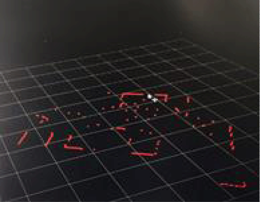
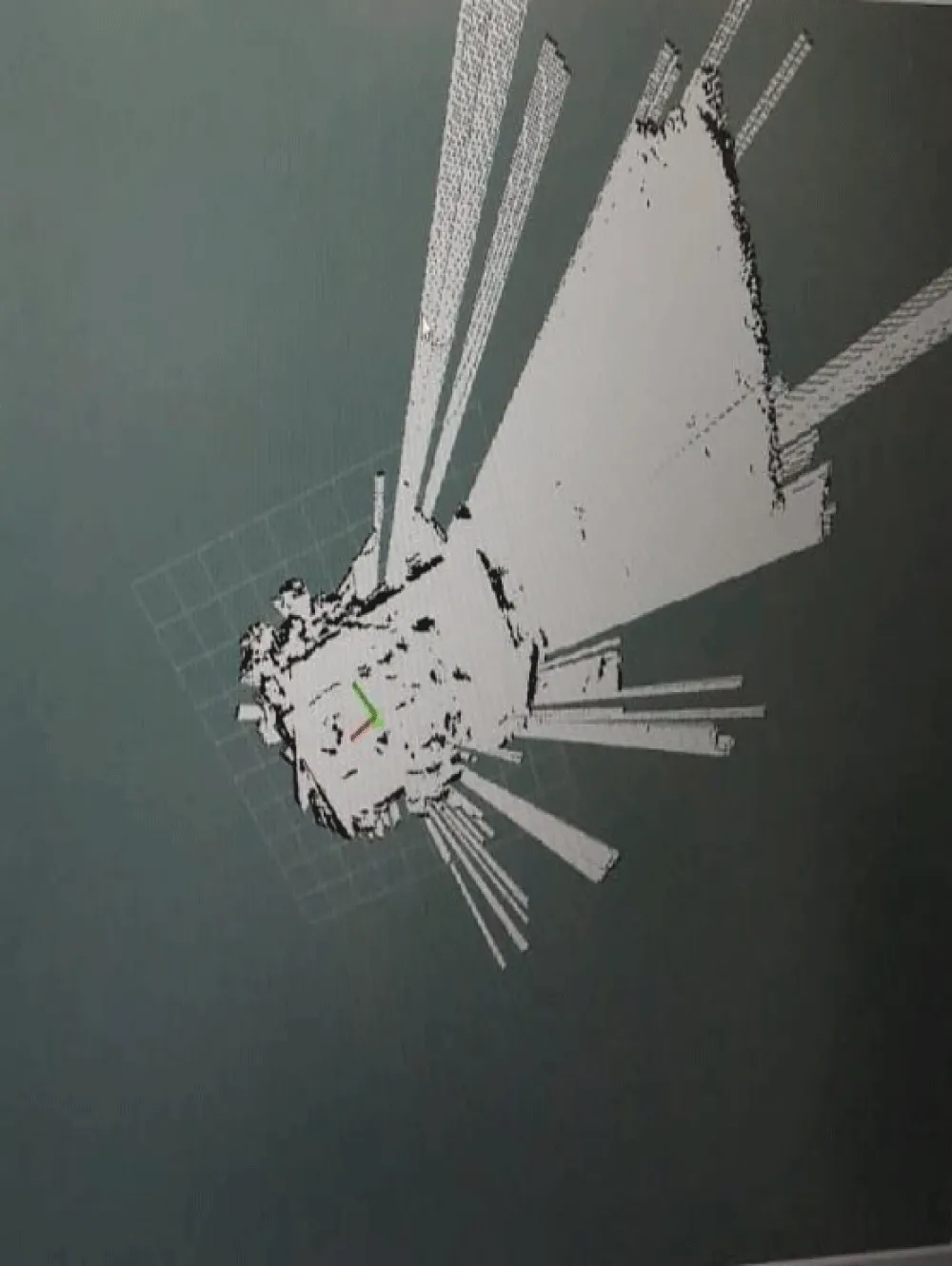
The output generated by LiDAR Hector SLAM shown in Figures 3,4, holds a crucial role, wherein it is converted into an occupancy grid. This occupancy grid, serving as a two-dimensional representation of the robot’s environment, forms the foundation of our path planning and obstacle avoidance systems in the robot’s navigation. Through the conversion of Hector SLAM data into this grid, the robot is endowed with a comprehensive understanding of its surroundings, enabling informed decisions to be made in real time. The integration of LiDAR data and occupancy grid mapping significantly bolsters the robot’s autonomy, allowing obstacles to be identified and optimal paths to be charted, thereby ensuring safety and efficiency in its movements.
B. LIDAR scan data
Each data point in a lidar scan data set typically includes information about the 3D coordinates (x, y, z) of the point, the intensity of the returned laser pulse, and sometimes additional attributes like the return number and scan angle. Lidar scan data is commonly represented as a 3D point cloud, which is a collection of these data points in a Cartesian coordinate system [20]. These point clouds can be used to create detailed and precise 3D models of the environment. Lidar scans are often taken at specific angles, and this information is typically included in the data. Scan angle data helps in determining the direction from which the lidar sensor acquired each point. The timestamp at which each data point was acquired can be included to help with data synchronization or time-based analysis. Range data is a collection of distance measurements [21]. Each measurement represents the distance from the lidar sensor to a specific point or surface in the environment. Rosinit is used to initialize ROS, and by default, a ROS master is created in MATLAB, along with the initiation of a global node that is linked to the master. The global node is automatically employed by other ROS functions. All nodes within the ROS network can be viewed using rosnode list, with the initial node being the global node generated by rosinit [6,22,23]. To observe the available topics in the ROS network, a rostopic list can be used. There are four active topics: /pose, /rosout, /scan, and /tf. The default topics, rosout, and tf, are consistently present within the ROS network. Specific details about a particular topic can be obtained by executing rostopic info, which, when used, demonstrates that /node_1 publishes messages. to the /pose topic, while /node_2 subscribes to that topic for message reception.
C. HECTOR SLAM data
The hector SLAM output of this project is given in the Figure 5. Hector SLAM is a real-time SLAM algorithm used for mapping an environment and localizing a robot within that environment. Hector SLAM was developed for mobile robots, especially those with 2D Lidar sensors, and is known for its efficiency and accuracy. Hector SLAM uses a scan-matching approach to build and update the occupancy grid map. It correlates consecutive Lidar scans to estimate the robot’s pose (position and orientation) and the location of obstacles on the map. This is done by aligning the new scan with the previously built map. Simultaneously with mapping, Hector SLAM performs robot localization. It estimates the robot’s pose within the environment by comparing the current Lidar scan with the previously created map. This information is crucial for the robot to know where it is on the map.
A robot may construct an accurate depiction of the environment, including the location and shape of objects, by integrating many Lidar scans to generate a precise map of the surrounding area. Lidar data is also necessary for path planning and navigation algorithms. Lidar scan data can be used by robots to plan collision-free routes across their surroundings [24]. To increase the accuracy of the maps it generates, Hector SLAM uses methods such as loop closure detection. This aids in fixing mistakes that have accumulated over time. It is capable of adapting to environmental changes, including moving objects and updating the map as necessary. Autonomous systems rely on Lidar scan and Hector SLAM data to comprehend and navigate their surroundings. Hector SLAM uses real-time processing of the extensive spatial information provided by Lidar to produce precise maps that allow the robot to locate itself inside it. This is essential for efficient and safe navigation in a variety of applications, such as robotic systems, drones, and autonomous cars. The future scope of the project is to automate the robot to change its direction when an obstacle is found in the direction in which the robot traverses [25]. This can be done by communicating the output received from Simulink back to the robot developed by making use of a motor driver. The mapping that can be obtained from Hector SLAM helps in providing a detailed representation of the environment, thus enabling path planning, aiding in localization, facilitating collision avoidance, and ensuring the robot has an up-to-date understanding of its surroundings [25,26]. This will make the robot to be used in geofencing applications in the military. Digital twinning provides a valuable framework for enhancing the capabilities of military robots operating within geofenced areas. It improves their ability to navigate, adapt to changing conditions, and contribute to the success of military missions while maintaining a high level of safety and efficiency.
Conclusion
The data from the Lidar is displayed using rviz. We could visualize the mapping of the data obtained. This data has to be brought to MATLAB using ROS. The Simulink model takes scan and pose data from the Lidar and helps us to predict the robot’s behavior. Here the model developed makes use of a reinforcement learning algorithm and pure pursuit algorithm to move towards its target. Also, the robot is given the occupancy grid that replicates the environment and the existing path in which the robot could move. Any new obstacle found will be displayed in the grid. Thus, digital twinning technology helps in real-time remote monitoring and also helps to predict the performance of the robot in an uncertain situation. To automate the robot to change its direction when an obstacle is found in the direction in which the robot traverses. This can be done by communicating the output received from Simulink back to the robot developed by making use of a motor driver. The mapping that can be obtained from Hector SLAM helps in providing a detailed representation of the environment, thus enabling path planning, aiding in localization, facilitating collision avoidance, and ensuring the robot has an up-to-date understanding of its surroundings.
- Abdulnabi, Sujatha BR. Autonomous Army robot with Geo-fencing technology. IJARCCE. 2021; 10: 855-862.
- Kousi N, Gkournelos C, Aivaliotis S, Lotsaris K. Digital Twin for Designing and Reconfiguring Human–Robot Collaborative Assembly Lines. Applied Sciences. 2021; 11(10): 4620.
- Digital twin for Interacting Mobile Robots (2023) Odense Robotics. https://www.odenserobotics.dk/projects/digital-twin-for-interacting-mobile-robots/.
- Ramesh A. Mathematical Modelling and Control of a Mobile Robot for Path Tracking. 2013;5
- Emara MB. Digital twinning for closed-loop control of a three-wheeled omnidirectional mobile robot, Procedia CIRP. 2022. https://www.sciencedirect.com/science/article/pii/S2212827122004231.
- Girletti L, Groshev M. An Intelligent Edge-based Digital Twin for Robotics. 2020 IEEE Globecom Workshops (GC Wkshps).
- Get started with Ros Get Started with ROS - MATLAB & Simulink. https://www.mathworks.com/help/ros/ug/get-started-with-ros.html.
- Ros Robotics projects. https://subscription.packtpub.com/book/iot-and-hardware/9781783554713/8/ch08lvl1sec62/getting-started-with-the-ros-matlab-interface.
- González R, Mahulea C. A MATLAB-based interactive simulator for Mobile Robotics. 2015 IEEE International Conference on Automation Science and Engineering (CASE). https://www.semanticscholar.org/paper/A-Matlab-based-interactive-simulator-for-mobile-Gonz%C3%A1lez-Mahulea/1278348e149e7cf281e75b0785f75c877e0eecb6
- Stateflow Onramp Self-Paced Online Courses - MATLAB & Simulink. https://matlabacademy.mathworks.com/details/stateflow-onramp/stateflow
- Path following with obstacle avoidance in Simulink® Path Following with Obstacle Avoidance in Simulink - MATLAB & Simulink. https://www.mathworks.com/help/nav/ug/path-following-with-obstacle-avoidance-in-simulink.html.
- Kholandy A. Mobile Robot Simulation and Controller Design with MATLAB Simulink, Academia.edu. 2014. https://www.academia.edu/6834350/Mobile_Robot_Simulation_and_Controller_Design_with_Matlab_Simulink
- Ed (2023) Install Ros Noetic on Raspberry Pi 4 - the robotics back, End. https://roboticsbackend.com/install-ros-on-raspberry-pi-3/
- Ed (2023b) Install Ubuntu 22.04 on Raspberry Pi 4 (without a monitor) - the robotics back, End. https://roboticsbackend.com/install-ubuntu-on-raspberry-pi-without-monitor/
- Castro S. Getting started with MATLAB, Simulink, and Ros, Student Lounge. 2017. Available at: https://blogs.mathworks.com/student-lounge/2017/11/08/matlab-simulink-ros/
- Filename Open and parse rosbag log file - MATLAB. https://www.mathworks.com/help/ros/ref/rosbag.html
- Chaiprabha K, Chancharoen R. A deep trajectory controller for a mechanical linear stage using digital twin concept, MDPI. 2023. https://www.mdpi.com/2076-0825/12/2/91 (Accessed: 19 January 2024).
- Raspberry Pi - GPIO connectorTutorialspoint. https://www.tutorialspoint.com/raspberry_pi/raspberry_pi_gpio_connector.htm
- Rplidar A1M8-R6 360 degree LIDAR Laser Range Scanner (12m). http://obrotu.com/rplidar-a1m8-r6-360-degree-lidar-laser-range-scanner-ss-NOnAV9F9.
- Pi Read Lidar Laser Scan Data Over ROS from Raspberry Pi - MATLAB & Simulink Example. https://www.mathworks.com/help/supportpkg/raspberrypi/ref/read-lidar-laser-scan-data-over-ros-from-raspberry-pi.html.
- Kousi N, Gkournelos C, Aivaliotis S, Digital twin for adaptation of robots’ behavior in flexible robotic assembly lines. Procedia Manufacturing. 2019; 28: 121-126. https://www.sciencedirect.com/science/article/pii/S2351978918313623 (Accessed: 19 January 2024).
- rde Koning R, Torta E, Pauwels P, Hendrikx RWM, van de Molengraft MJG. Queries on Semantic Building Digital Twins for Robot Navigation. 2021; 3081: 32-42. https://pure.tue.nl/ws/portalfiles/portal/197547153/CIB_W78_2021_paper_78.pdf
- Baidya S, Das SK, Uddin MH, Kosek C, Summers C. Digital Twin in Safety-Critical Robotics Applications: Opportunities and Challenges. 2022 IEEE International Performance, Computing, and Communications Conference (IPCCC).
- Alsaleh S, Tepljakov A, Tamre M, Kuts V, Petlenkov E. Twin D. Simulations Based Reinforcement Learning for Navigation and Control of a Wheel-on-Leg Mobile Robot. Asmedigitalcollection.asme.org. https://asmedigitalcollection.asme.org/IMECE/proceedings/IMECE2022/86649/V02BT02A025/1156863
- Avila EA, Chapa rDP, Arenas ID, Hurtado CV. A Digital Twin implementation for Mobile and collaborative robot scenarios for teaching robotics based on Robot Operating System. 2022 IEEE Global Engineering Education Conference (EDUCON). https://ieeexplore.ieee.org/document/9766583/
- Digital Twinning for Common Robot Applications (no date) Yaskawa Motoman Robotics. https://www.motoman.com/en-us/about/blog/digital-twinning-for-common-robot-applications.

Article Alerts
Subscribe to our articles alerts and stay tuned.
 This work is licensed under a Creative Commons Attribution 4.0 International License.

 Save to Mendeley
