Annals of Robotics and Automation
An Experimental Study on Surveillance Robot Using Raspberry Pi
Soroosh Mahmoodi1-3*, Malala Stembinkosi Shapola2, Parisa Hamedia2
2Jiangxi University of Science and Technology, Ganzhou 341000, Jiangxi, PR. China
3Soroosh Khorshid Iranian Co, Abyek Industrial Zone, Qazvin, Iran
Cite this as
Mahmoodi S, Shapola MS, Hamedia P (2022) An Experimental Study on Surveillance Robot Using Raspberry Pi. Ann Robot Automation 6(1): 001-006. DOI: 10.17352/ara.000015Copyright
© 2022 Mahmoodi S, et al. This is an open-access article distributed under the terms of the Creative Commons Attribution License, which permits unrestricted use, distribution, and reproduction in any medium, provided the original author and source are credited.Recently, robots have been developed to reduce human resources and observation time in a fast, booming, and rapidly growing technology. In this study, a surveillance robot is designed and manufactured to move around a given surrounding, preferably a domestic environment, record video & audio and send the information to the user through a network. The robot is allowed to be controlled wirelessly using Raspberry Pi technology from a location remotely using IoT technology. This sensor-based robot uses the Raspberry Pi with Ethernet, WI-Fi and Bluetooth for networking purposes. Python is chosen as the programming language in both autonomous and semi-autonomous modes. The manufactured robot was experimentally tested. The recorded videos, images and audio are successfully transferred through a WiFi network to the end user. The user could also control and move the robot in different directions for specific demands. The designed simple robot interests users to record and transfer information for the safety of their indoors.
Introduction
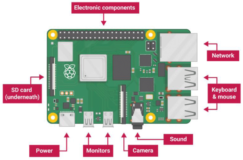
A robot is an automatic electronic machine that senses environmental changes through related sensors. The robots are programmed to act while perceived values are lower or higher than a particular value. The programmers start their idea by drawing a flow chart and then design appropriate algorithms to reduce the complexity and iteration of their program [1-4]. Logic circuits, electronic components and programming are the essential parts of a robot. Recently, surveillance robots have become an increased interest of many users for different applications. Surveillance is a process of close systematic monitoring, observation, or supervision maintained over a person or an environment to protect, act and send information to the users. The users can interact with the robot using computers or smartphones over a Wi-Fi network. By programming embedded systems, surveillance robots can be employed for indoor and outdoor applications [5-6]. The surveillance robots mainly consist of a microcontroller such as Raspberry Pi or Arduino, which is the programmable brain of the robot. The Raspberry Pi is a low-cost, small card-like piece-sized computer that enables the users to be connected to a computer, monitor, camera, WiFi rotors and so on for controlling robots, image processing and many other applications [7-12]. A schematic of the standard Raspberry Pi board and its different ports are shown in Figure 1. Open CV (Open-Source Computer Vision Library) is a programming method used to run the Raspberry Pi board for computer vision purposes. Open CV is a library of programming functions mainly aimed at real-time computer vision [13].
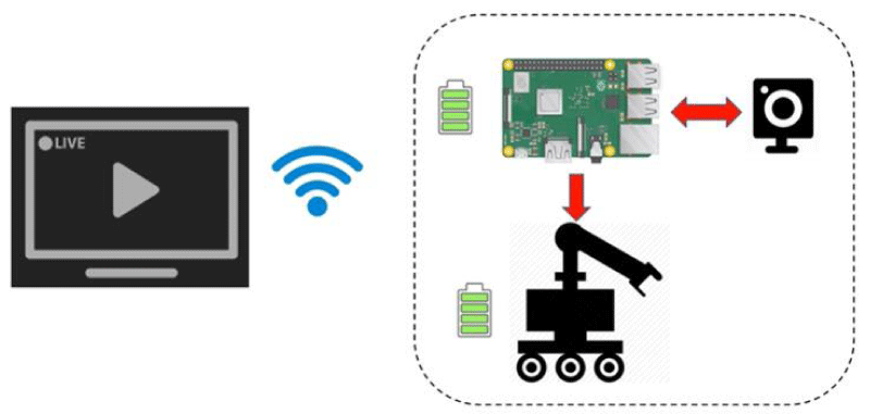
In this experimental study, a simple robot is assembled using a Raspberry Pi board as the brain of the surveillance robot. A pi camera is installed on the robot’s chassis. The open CV is installed on the Raspberry Pi for image processing applications. Python is employed to program the Raspberry Pi for robot motion and control applications. The user receives the digital data, images, videos and audio on a computer through a WiFi network. Figure 2 shows the designed system and the relation of different accessories of the robot.
Robot accessories requirement and assembling
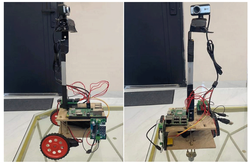
The hardware requirements of this robot such as a Raspberry Pi board, a pi web camera, two DC motors, Caster Wheels, a DC motor driver circuit, a 9V battery, battery connectors, wooden chassis, single pin connectors and so on were purchased. The robot hardware and accessories are assembled. The Raspberry Pi board is connected to the pi camera, the DC motor driver circuits, battery, and WiFi. The chassis of the surveillance robot is equipped with two wheels driven by the DC motors pinned to the motor driver circuit. The motors are interfaced with the Raspberry Pi’s General-Purpose Input and Output (GPIO) pins. The Raspberry Pi controls the robot’s movement by sending appropriate signals to the DC motors. The LED light of the Raspberry Pi board shows specific colors in different circumstances. The connections between the Raspberry Pi, robot motion system, pi camera, and computer are shown as a schematic in Figure 3. Table 1 shows brief and important conditions while connecting the Raspberry Pi board to other accessories. Raspbian OS and Python compiler were installed as the software requirements. The Raspberry Pi is interfaced with a webcam. It captures videos from the webcam for live streaming. The Raspberry Pi is connected to a computer through WiFi and uses a virtual network connection viewer as its tool. The computer accesses the pi as a virtual machine, so the video captured by the webcam is a live stream on the laptop’s screen. The photo of the assembled surveillance robot is shown in Figure 4.
Logical programming of robot motion in different directions
The robot is controlled by the keys pressed on the end user’s (laptop) keyboard. This section defines the logical programming of the robot’s motion in different directions (forward, backward, left, right and stop).
The forward motion of the robot is logically defined as the following. The positive terminal of the left wheel should be induced with a high signal and the negative terminal with a low one. The left motor is connected to pins 38 and 40, so pin 38 should be induced with the high signal and pin 40 with the low one. Furthermore, the positive terminal of the right wheel should be induced with a high signal and the negative terminal with a low one. The right motor is connected to pins 35 and 37, so pin 35 should be induced with a high signal and pin 37 with the low one. Figure 5 shows the logical programming of the robot to go forward.
The backward motion of the robot is logically defined as the following. The backward movement logic is precisely the opposite of the forward movement. For the left motor, Pin 38 should be induced with a low signal and pin 40 with a high one. For the right motor, pin 35 should be induced with a low signal and pin 37 with a high one. Figure 6 shows the logical programming of the robot to go backward.
The robot’s motion to the left is logically defined as the following. The right motor should move in the forward direction and the left motor in reverse. Therefore, the robot starts to turn left. In this case, the positive terminal of the left motor should be induced with a low signal and the negative terminal with a high one. The positive terminal of the right motor should be induced with a high signal and the negative terminal of the right motor with a low one. Therefore, the Raspberry Pi pins of 38 and 40 for the left motor should be low and high, respectively. The pins of 35 and 37 should be high and low, respectively. Figure 7 shows the logical programming of the robot to go left.
The robot’s motion to the right is logically opposite of the left motion, as follows. Therefore, the Raspberry Pi pins of 38 and 40 for the left motor will be induced with high and low signals, respectively. The pins 35 and 37 of the Raspberry Pi should be induced with low and high signals, respectively. Figure 8 shows the logical programming of the robot to go right.
The stop order of the robot is logically defined as follows. Both terminals of both motors should be induced with a low signal to stop the robot. Figure 9 shows the logical programming of the stop robot.
Programming aspects, results and discussions
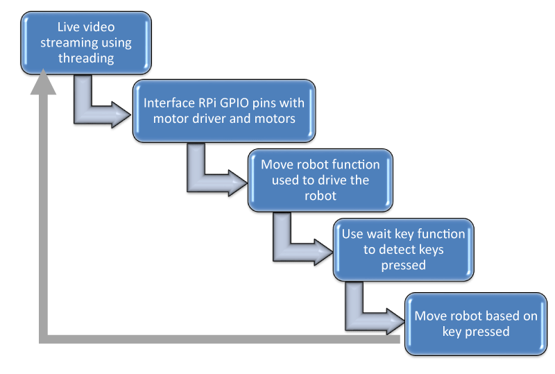
Python was chosen as the programming language of the surveillance robot. The threading is used to decrease the latency of streaming. The modules and program functions are shown in Figure 10.
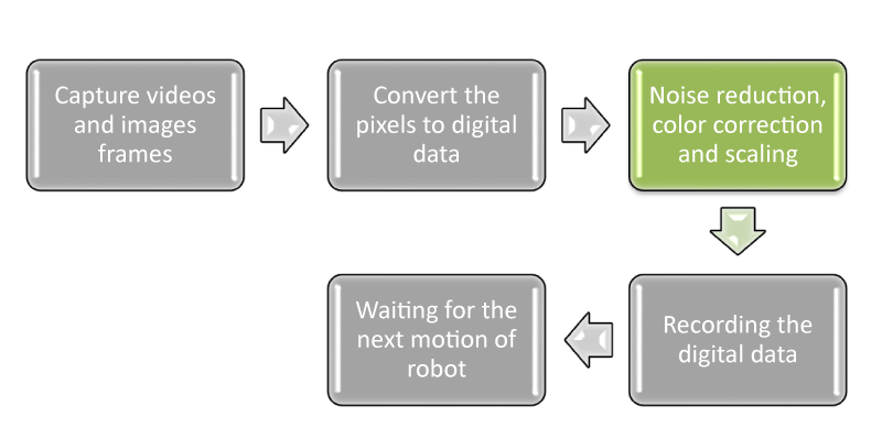
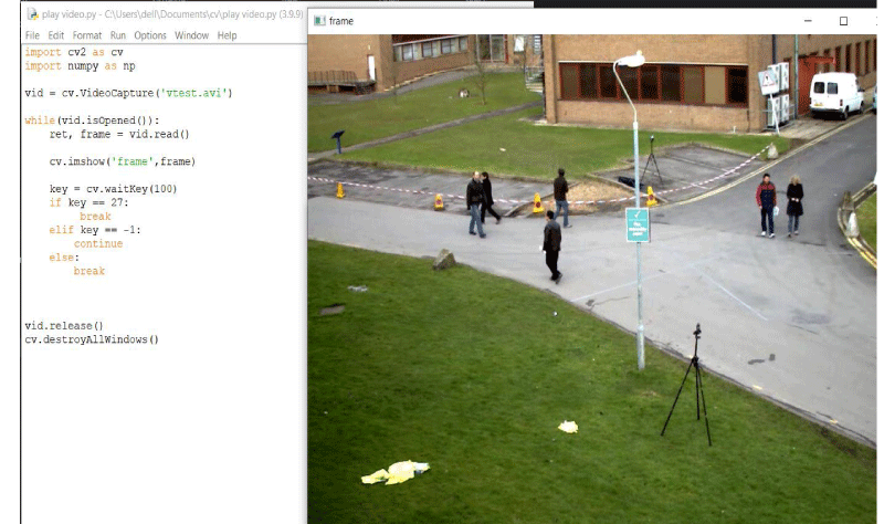
A computer vision pipeline is a sequence of steps that computer vision applications would define. Most computer vision applications begin with capturing videos or images and converting the pixels to digital data. Then, the digital data would be processed and analyzed depending on the programmer’s aims. The general pipeline of the image processing of this study is shown in Figure 11. Open CV has been employed and installed on the Raspberry Pi for capturing video and accessing the pixels of the images. Figure 12 shows the robot’s camera-captured image using the Open CV on the user’s monitor.
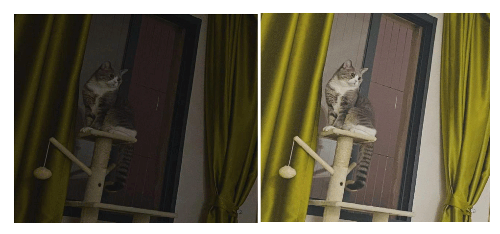
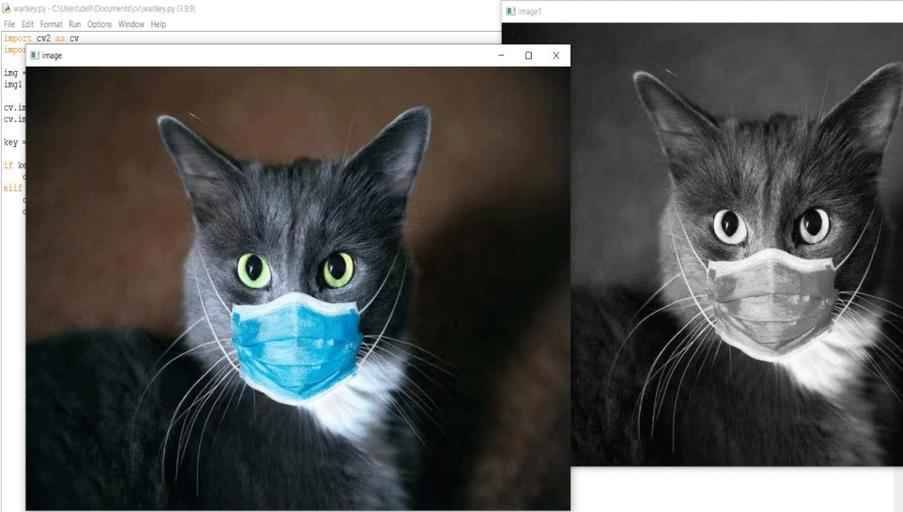
The manufactured surveillance robot was experimentally tested indoors. The audio, videos, and images were successfully transferred through a WiFi network to the end user. The Raspberry Pi board using the Open CV was programmed to filter noises and increase the resolution of captured images. Figure 13 shows the received image of computer vision from the surveillance robot on the user’s screen (laptop) at night (left image). The right embodiment of Figure 13 shows the same image after noise filtering and resolution enhancement while focusing on an object (the cat). Moreover, the robot using the Open CV could record images in a colorful or greyscale style. Figure 14 Shows the transferred image from the surveillance robot in both colorful and greyscale styles.
Conclusion
An indoor two-wheel surveillance robot that can be easily operated on a computer was designed and fabricated. The image processing property of this experimental study allowed the user to view real-time videos and images. A Raspberry Pi board was employed as the control unit of robot movement and output information. The robot could be navigated to record data from different regions using python and its modules. A pi camera is interfaced to record audio, images and videos and export them to digital signals. Live streaming video at day and night times with a mounted camera could be recorded. The digital signals were transmitted to the end user within the Raspberry Pi’s general-purpose input and output pins through a WiFi network.
The robot often takes time to respond to directions right, left and stop according to its wait key setup. In this case, because a program runs fast while the robot takes time to respond, the delay time is increased to 120 milliseconds, which leads to the robot’s response matching the program execution. The power supply is a vital issue for the parallel usage of Raspberry Pi and other hardware components such as DC motors. An equal amount of power is needed for all the components to work properly. The garbage collection in Raspberry Pi, which was accumulated at the output field, was one of the biggest challenges. It made the control of robots becomes complicated. The problem could be solved with the open-source capabilities of Raspberry Pi, which allows for the installation and running of the Raspberry Pi trash classifier. The Raspberry Pi trash classifier could assist in getting rid of the garbage or recycling the data. This experimental study has the ability of industrialization, which needs further investigation.
- Li W, Xia L, Huang Y, Mahmoodi S. An ant colony optimization algorithm with adaptive greedy strategy to optimize path problems. J Ambient Intell Human Comput. 2022; 13:1557–1571. https://doi.org/10.1007/s12652-021-03120-0
- Li W, Meng X, Huang Y, Mahmoodi S. Knowledge-guided multiobjective particle swarm optimization with fusion learning strategies. Complex Intell. Syst. 2021; 7:1223–1239. https://doi.org/10.1007/s40747-020-00263-z
- Li W, Sun B, Huang Y, Mahmoodi S. Adaptive complex network topology with fitness distance correlation framework for particle swarm optimization. Int J Intell Syst. 2022; 37: 5217- 5247. doi:10.1002/int.22790
- Yan X, Li W, Huang Y, Mahmoodi S. “An Adaptive Parameter for Max-Min Elite Ant System to Solve CVRP Problem,” 2021 17th International Conference on Computational Intelligence and Security (CIS). 2021; 580-584. DOI: 10.1109/CIS54983.2021.00126.
- Dixit DSK, Dhayagonde SB. Design and implementation of e-surveillance robot for video monitoring and living body detection. International Journal of Scientific and Research Publications. 2014; 4(4):1-3.
- Ohaneme CO, Eke J, Azubogu ACO, Ifeagwu EN, Ohaneme LC. Design and implementation of an IP-based security surveillance system. International Journal of Computer Science Issues (IJCSI). 2012; 9(5):391.
- Richardson M, Wallace S. Getting started with raspberry PI: O'Reilly Media. Inc. 2012.
- Gonzalez RDipNY, NY: Pearson. ISBN 978-0-13-335672-4.
- Gonzalez RCaREW, «Digital Image Processing», Second Edition. 2006.
- Alhasnawi BN, Jasim BH. SCADA controlled smart home using Raspberry Pi3. Proceedings of the 2018 International Conference on Advance of Sustainable Engineering and Its Application (ICASEA). Wasit-Kut. Iraq. 2018; 14–15.
- Alhasnawi BN, Jasim BH. Wireless controlled smart home system, Iraqi Journal for Electrical and Electronic Engineering. 2017; 13:1.
- Alhasnawi BN, Hani B. “Wemos-d1 and raspberry pi3 based smart communication and control of home appliances system “, Muthanna Journal Of Engineering And Technology. 2018; 6:1; 29-44,.
- Pulli KB, Anatoly, Kornyakov, Kirill, Eruhimov. Victor. “Real-time Computer Vision with OpenCV”. Queue. 2012;10 (4): 40:40-40:56. doi:10.1145/2181796.2206309.

Article Alerts
Subscribe to our articles alerts and stay tuned.
 This work is licensed under a Creative Commons Attribution 4.0 International License.



 Save to Mendeley
