Journal of Civil Engineering and Environmental Sciences
Examination of hydrodynamic behavior of wind deflectors in the normal inner temperature with the point of more efficiency
(Case study: Bwhsa Köppen climate classification of Kashan City)
Mohammadali Karbasforoushha*
Cite this as
Karbasforoushha M (2023) Examination of hydrodynamic behavior of wind deflectors in the normal inner temperature with the point of more efficiency (Case study: Bwhsa Köppen climate classification of Kashan City). J Civil Eng Environ Sci 9(2): 052-062. DOI: 10.17352/2455-488X.000068Copyright License
© 2023 Karbasforoushha M. This is an open-access article distributed under the terms of the Creative Commons Attribution License, which permits unrestricted use, distribution, and reproduction in any medium, provided the original author and source are credited.One of the ways to achieve a building with higher energy efficiency and an efficient system is to use local architectural experiences. In the meantime, a wind deflector is one of the elements used in the past to create comfort. In the Bwhsa Köppen climate classification of Kashan City, they used to move and cool the air in the building. This study investigates the interior of these settlements in this climate to aim to reach greater efficiency of this element by CFD software, Energy Plus, and Open Studio with a descriptive-analytical method and then analyzes the results. A comparison of the results of the analysis of wind speed in wind turbines and how the wind is oriented in the interior is shown. Due to the low thermal mass of the wind deflector walls compared to the room, the temperature fluctuation is always higher than in the room. The main factors in temperature drop are proportionality of dimensions-air inlet valve to the windshield, water temperature, measurements, and height of the windshield column. Finally, to reduce the room temperature further, the priority is to use a spray windshield over windshield wipers. Especially windshields with water spray in which most of the room has a temperature of 25 degrees Celsius and are in Kashan city’s thermal comfort range.
Introduction
The energy demand worldwide is rising at a rapid pace. It is estimated to grow by up to 50% from 2018 until 2050 [1]. The building sector is responsible for a significant portion of the total energy consumption (40%) [2] Generally, conventional Heating, Ventilation, and Air Conditioning (HVAC) systems consume nearly two-thirds of the total building energy consumption [3]. Hence, many researchers are looking towards implementing natural ventilation and passive cooling strategies to reduce energy demand while providing thermal comfort [4,5] and improving Indoor Air Quality (IAQ) [6]. People spend 80% - 90% of their time in indoor spaces while working and living [7]; so, failure to provide good IAQ could affect their health, well-being, and productivity [8]. Natural ventilation does not only reduce the operating costs of a building, but it can also reduce the size and cost of mechanical ventilation systems [9]. Natural ventilation can be integrated into a building via different strategies such as a window, solar chimney, wind catcher, etc. The wind deflector is an architectural element that is installed on the roof of the building. It captures the fresh air from outside through its openings and directs it toward the interior space. At the same time, it extracts the stale air out of the space [10,11]. The main advantage of a windcatcher is that it can capture wind at a higher elevation as compared to lower-level windows or vents [12,13]. Two driving forces guarantee the continued operation of the wind deflector; wind force due to air pressure differences and buoyancy force due to temperature differences between the inside and outside of the building [13-16]. The induced air movement can directly raise convective and evaporative heat losses related to occupants, which leads to offset elevated operative temperature of interior space [17]. Wind deflector has been used for centuries in the Middle East to provide natural ventilation and passive cooling inside the building [18,19]. The first evidence of wind deflector application was found during the 1970s in the archaeological site of Tappeh Chackmaq (in the vicinity of Shahrood city) in the central part of Iran where it is guessed to have been constructed a hundred years ago [20,21]. Currently, modern wind deflectors with new design features can be seen in different areas of the world particularly in the UK, where hundreds of commercial wind deflectors have been installed in public buildings, educational spaces, and shopping malls [22,23]. Reyes, et al. [24] stated that one of the essential advantages of this green feature is that it can be scaled and adapted for many types of buildings. Wind deflectors are typically varied in cross-section, openings, and height according to location, wind speed, and direction [25]. A considerable number of studies have focused on the effects of different configurations and components on the wind deflectors’ performance using CFD modeling, analytical, and experimental approaches. Previous reviews [26] and [27] on wind deflectors focused on the effect of the wind deflector’s design on the thermal performance. Recently, with the advancement of computational and experimental methods, studies have started exploring the impact of external parameters on wind deflectors such as building roof shapes, the effect of other buildings or structures and upstream objects such as other wind deflectors which requires more computational resources and more extensive experimental facilities. Additionally, many works have attempted to improve the wind deflector’s ventilation efficiency by modifying its geometry such as the optimization of roof shape, interior partitions, and the addition of anti-short circuit devices. More studies have also been carried out to integrate wind deflectors with other natural ventilation systems such as courtyards, wing walls, and solar chimneys. This research intends to give useful recommendations to raise the effectiveness of this element to lower the average interior temperature of settlements, in addition to knowing and analyzing the structure of this approach and profiting from the experience of utilizing this component.
Method
As previously stated, this study aims to examine how well the wind deflector performs in lowering the residence’s average interior temperature in a hot, dry region to improve the effectiveness of this device by including a humidification system. As a result, in the first phase, assuming the summer season in this climate and the identical circumstances in Kashan’s hot and dry environment, assuming the outside air temperature is 313K, is under the physical character of this research (40°). Then, by including the moisture creation system, modeling, and analysis are performed once again, comparing these models to choose the model that performs the best.
Literature review
Wind deflectors have been the subject of in-depth research up to this point. Ayatollahi and Pour Ahmadi have reviewed the various wind deflector types, their spatial relationships with the interior building components, and their correction measures in-depth [28]. The distinctive characteristics of Yazd wind turbines have been discussed by Suzanne Roof, an English researcher who completed her doctoral thesis on “Yazd wind turbines” in 1988. She views these devices as traditional technologies that have been used to capture wind and direct airflow from the outside into buildings to create a building’s natural airflow [29]. Numerous research on wind turbines has been conducted by Mehdi Bahadrinejad [30]. Additionally, they have worked to develop two additional Yazd University wind deflectors, and the outcomes of their study have been shared in several scholarly papers [31]. The Dolat Abad garden wind deflector has been the subject of Kalantar’s short-term field and experimental studies, and he used the findings of his experiments to validate the numerical modeling. Additionally, they have researched how well the wind deflectors naturally evaporate heat [32]. The majority of the study that has been done so far by researchers on the function of wind deflectors in Iran is based on meteorological data, and few studies focus on integrating contemporary technologies with local knowledge. By combining contemporary technologies, this study, like earlier ones, seeks to improve the performance of local and climatic experiences.
Wind deflector structure
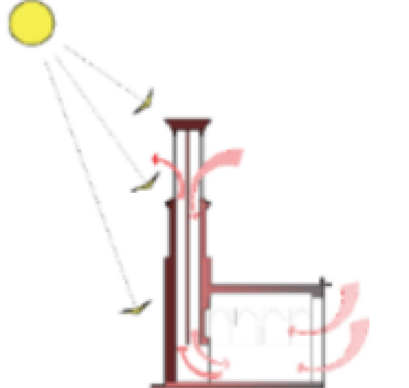
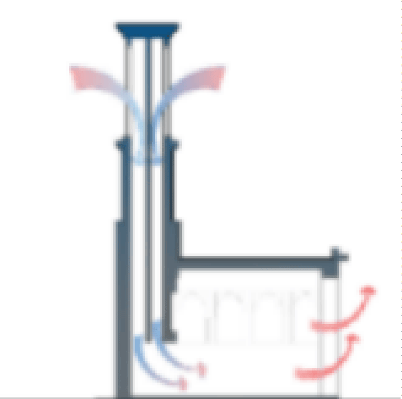
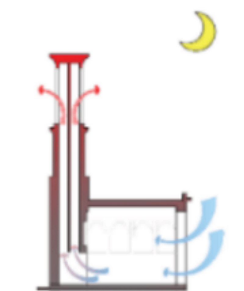
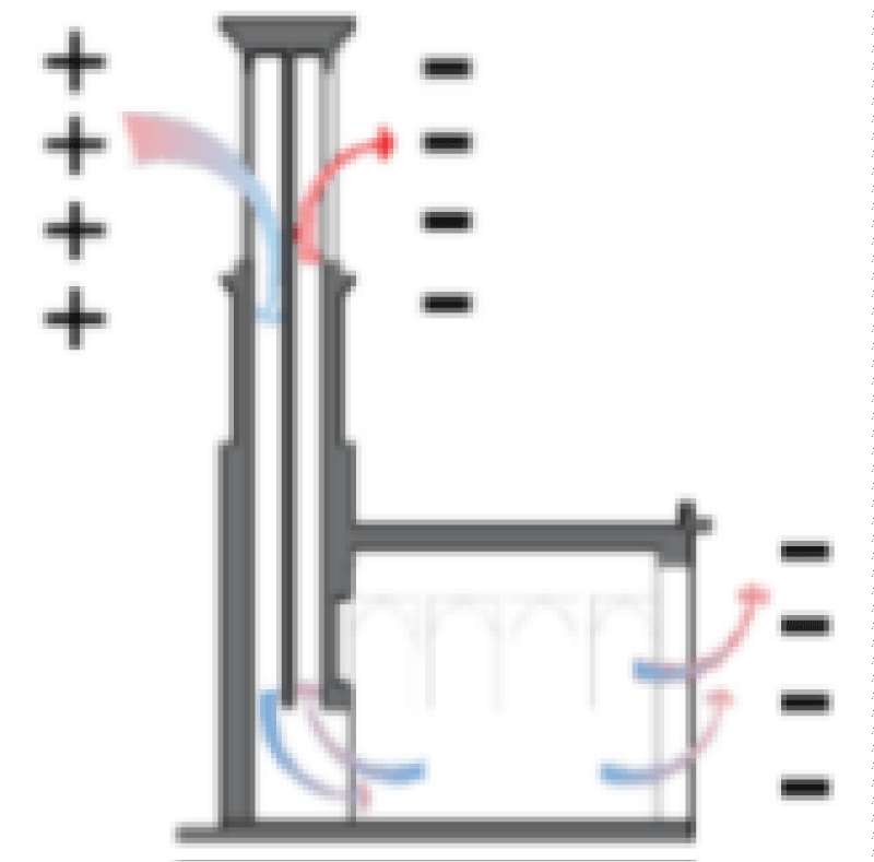
The design of wind deflectors allows the wind to enter via the holes in the structure and then be directed to a water-filled basin. This impact in hot and dry locations causes water to evaporate, lowering the wind’s temperature while raising its humidity. Finally, the chilly and humid breeze enters the summer rooms and cools the air inside [33]. Even if the wind speed outside is zero, the wind will still blow in a different direction throughout the day and at night. The air inside the wind deflector has a lower density than the air outside at the start of the night because of the thermal capacity of the wall’s materials and the sun’s ability to keep it warm. As a result of this density difference, the wind deflector functions as a ventilator and draws air from the inside to the outside. The air exits the wind deflector due to acquiring heat from the wind deflector and the building’s heated walls. Finally, the flow of cold air from the yard into the building occurs as long as the temperature of the wind deflector wall is higher than the outside temperature. The building wall and the wind deflector will finally cool as a result of this motion during the night (Table 1). The wind deflector works against the direction of the chimneys when the temperature of the wind deflector wall becomes the same temperature as the environment due to heat exchange, i.e., the wall becomes cooler than the ambient temperature inside the room. When this happens, the air inside the wind deflector becomes heavier than the temperature inside the room and descends due to the force of buoyancy. As a consequence, the wind deflector’s internal air pressure drops, allowing air to enter via the opening in the wind deflector and warm inside air to escape out the windows. This process will repeat in the morning [31]. The air will flow up and out of the wind deflector when the south side of the device is heated by the noonday sun and is warmer within the device than in the surrounding space. The wind deflector experiences a negative pressure, which causes the air within the home to ascend and be replaced by fresh air from the window [34]. Generally speaking, the pressure rises as the distance between the air input and the air exit increases with the height of the wind deflector [35]. Due to the development of negative pressure and the suction of heated interior air, wind deflectors with independent multi-channels cause the desired wind to enter from one direction and depart in the direction opposite to the wind [36]. Also, depending on how the wind deflector is positioned concerning the building and its main components, this circulation brought on by the pressure difference caused by the wind may operate in the opposite direction, with air entering through the door and window and exiting the wind deflector. The wind deflector will serve the same purpose as the ventilator in this instance. In actuality, the air enters the windshield through positive pressure valves and leaves through negative pressure valves or doors and windows [37].
Calculating the airflow speed in traditional wind deflectors
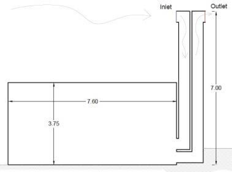
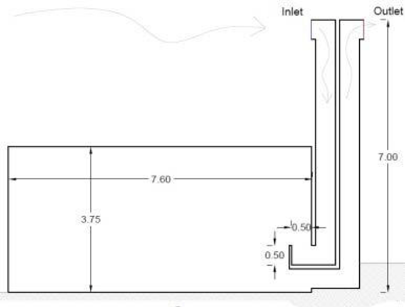
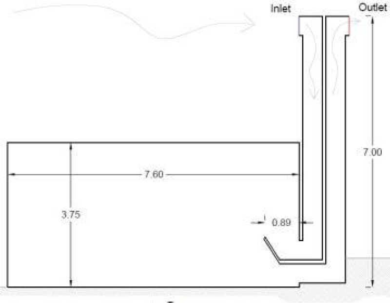
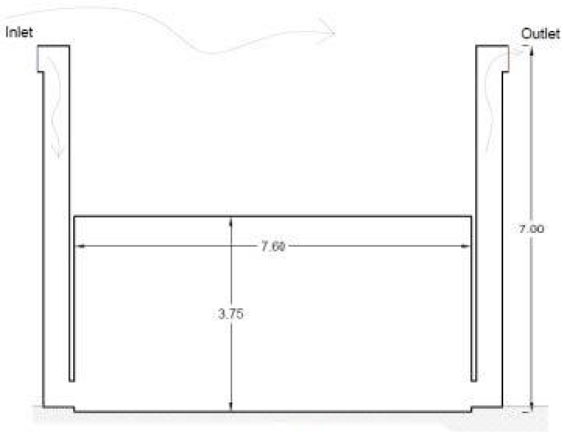
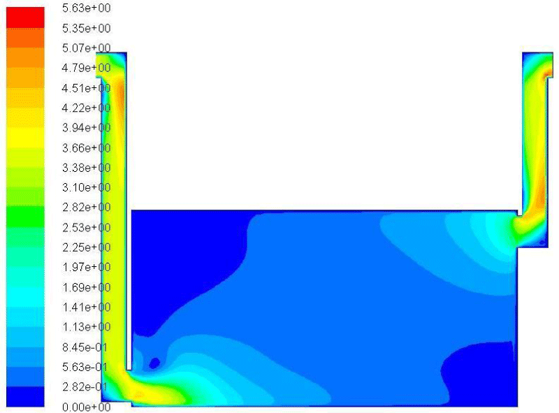
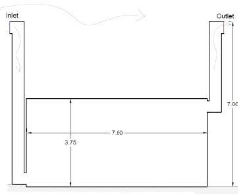
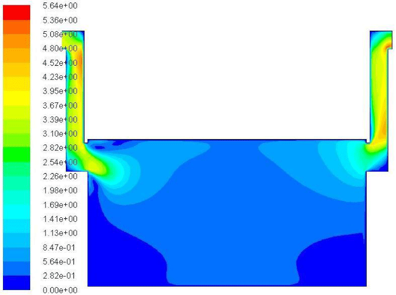
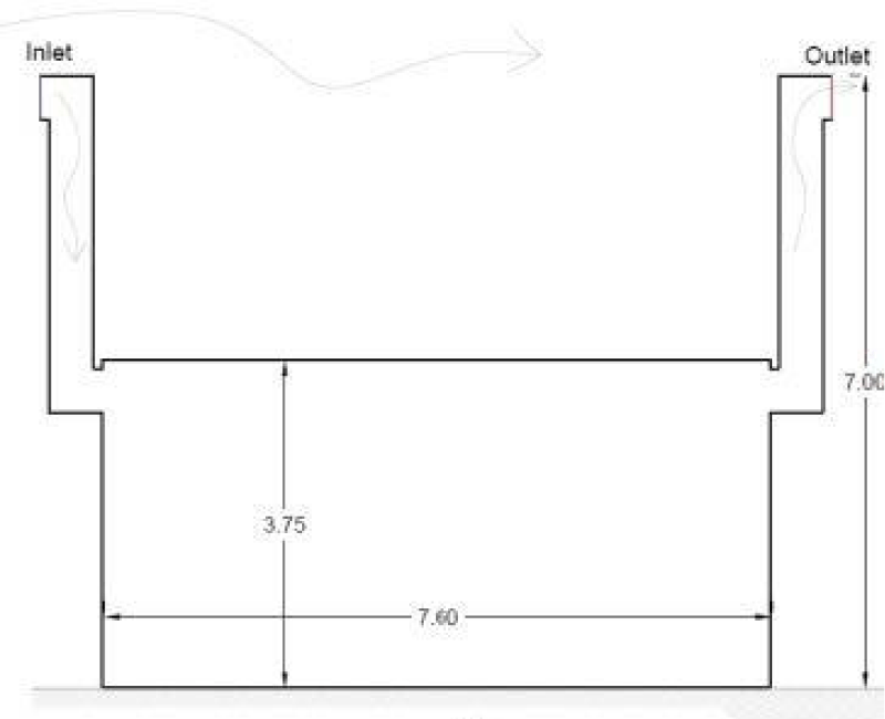
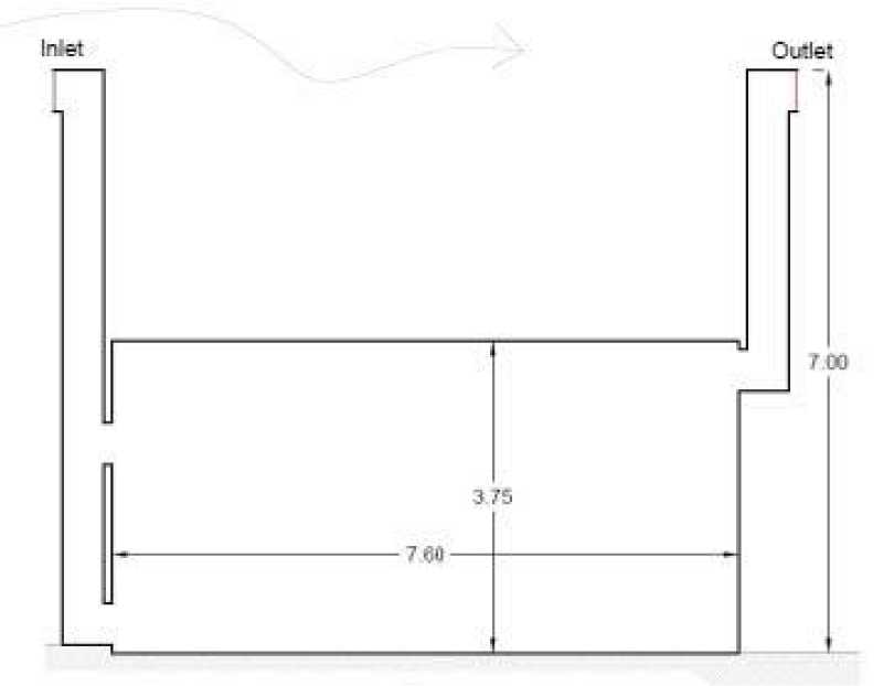
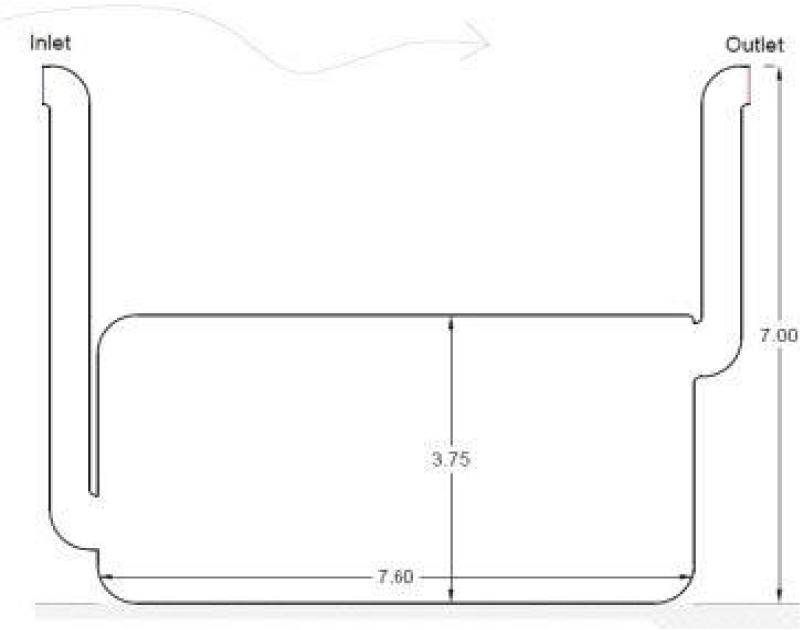
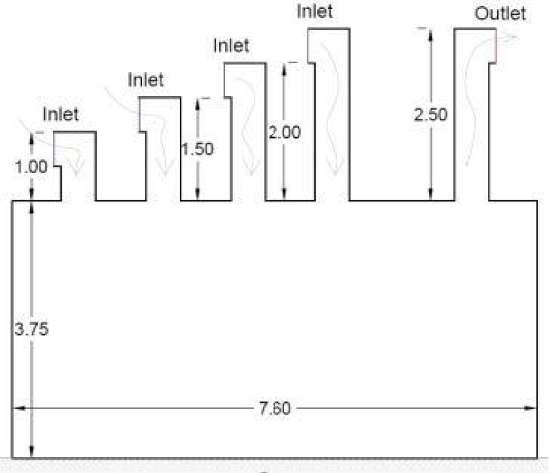
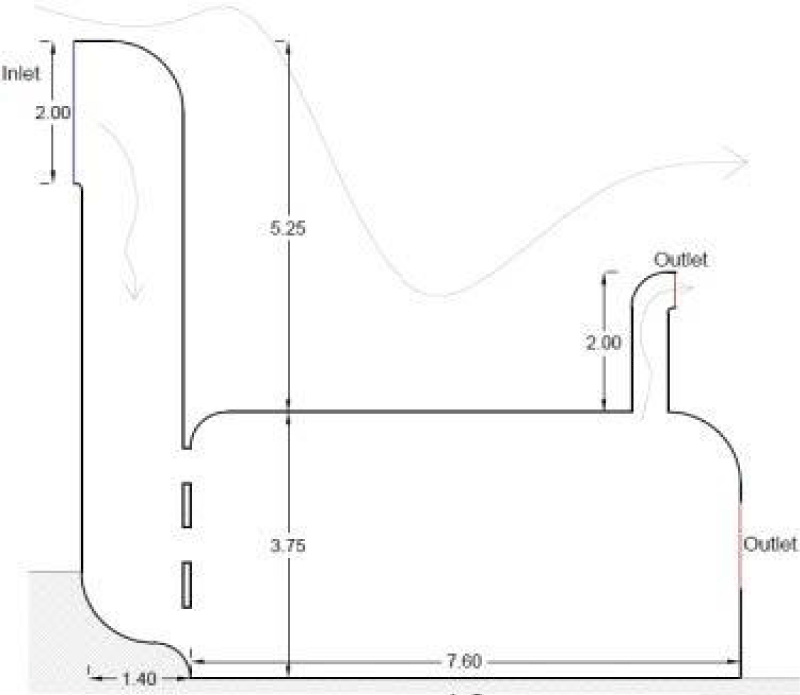
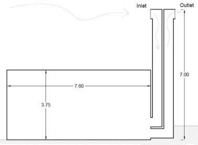
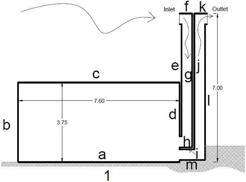
This part created and assumed 10 conventional wind deflector models and then used CFD calculation tools to assess the airflow speed in each of them in two dimensions. In each scenario, the room’s interior walls are 35°, its walls are 80 cm thick, and the entering airspeed is 455.3 m/s. The outside air temperature is 40° (the mean wind speed in the first six months of Kashan city). The air temperature inside the building is considered to be 39.8°, and convection heat transfer is established between the inner walls and the adjacent air. The room’s proportions are based on the summer settlement’s length and height in Kashan’s hot and dry environment, which are 3.75 m and 7.60 m, respectively. The room’s preferred wind direction is from left to right (Table 2). The entrance and exit valves, except for models 8 and 10, and the wind deflector column, except for model 10, each have a width of 50 cm.
The simulation results of traditional wind deflectors
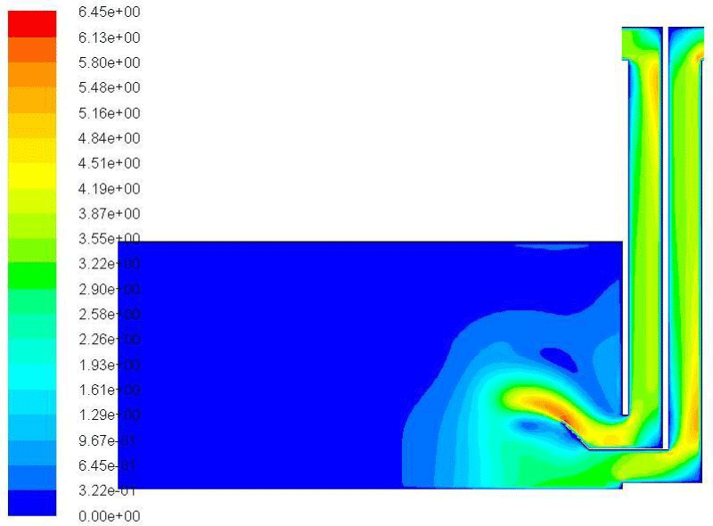
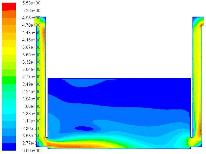
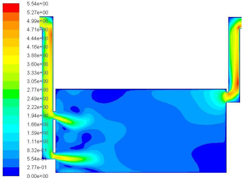
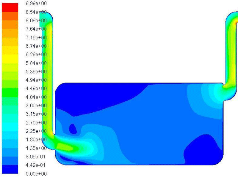
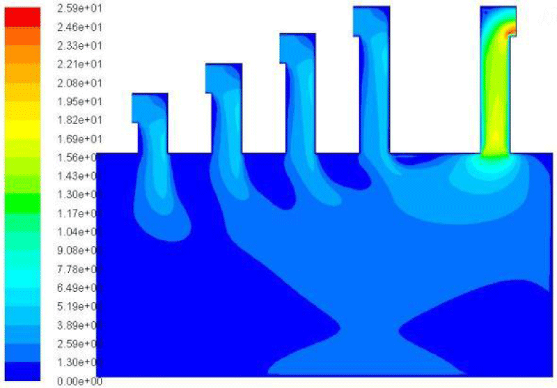
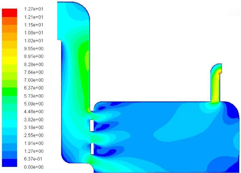
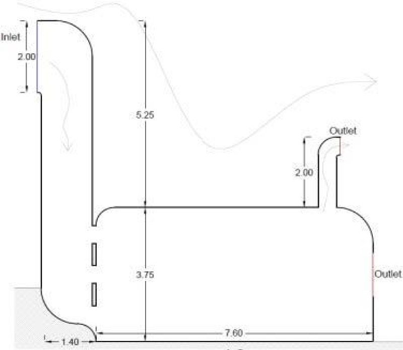
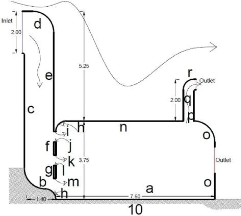
Models 1 through 3 (Table 3) are two-way wind deflectors that are mostly constructed in the direction of known winds. They are straightforward and practically modest in terms of architectural construction. In (model 1), the airflow enters at the top of the wind deflector column’s valve facing the wind and exits through the valve also facing the wind. The airflow is nearly entirely sucked out of the room as soon as it enters due to the proximity of the room’s exit valve to its entry, as can be seen from the contours of this model, and the room is almost unaffected by the airflow. Both wind columns have airflow that is faster than the input speed, which may be leveraged by clever design to organically move the fan or turbines. Additionally, the areas with the maximum wind speeds are those where the wind’s direction changes by a 90-degree angle. The airflow is considerably distant from the outlet in (Model 2) due to the partition wall that has been built between the room’s air input and exit valves. As a consequence, half of the room is influenced by the incoming airflow. In this instance, the intake valve partition region toward the center of the room experiences a maximum speed that is roughly double the ambient speed. The second half of the space, however, is still filled with motionless air (0.3 - 0.0 m/s). The wind-affected region is made smaller and nearer to the outflow area by rotating the partition blade (model 3) by 45 °C. Additionally, there is a bigger proportion of airflow than before at the top corner of the input valve. By analyzing the aforementioned three scenarios, it can be said that the closeness of the air intake room’s inlet and outflow does not adequately support the room’s airflow. They may therefore be placed apart for improved room flow. To achieve this, one-way wind deflectors were created, and the air input and outflow columns were positioned as far apart from one another as possible. Both wind-catcher columns in (Model 4) are equally tall and long. Due to the intake and exit vents being placed in opposition to one another, a wind flow develops at the room’s floor up to a height of slightly more than half (the range of use by the users of the space). The largest flow occurs in the broadest region near the entry valve, at m/s 2.5 - 2.5, in the lower layers near the bottom of the room, at 1.1 - 2.2 m/s, in the intermediate layers of the room, at m/s 0.1 - 27.1, and in the upper portion of the room, where there is virtually no flow at all (0.27 - 0 m/s). The room’s bottom-to-top wind flow slows down as it moves away from the input and exhaust valves. In (Model 5), the airflow between the two ventilation columns is created by positioning the room’s outlet valve close to the ceiling (shortening the outlet column and utilizing the room’s natural air circulation), and only two of the room’s corners have a speed of 0.28 - 0 m/s. Near the vents, the wind speed is 0.4 - 0.84 m/s, and it is at its highest in the wind-catcher columns. The wind speed is around 0.84-0.28 m/s where space users are located. The two lower corners of the room in (Model 6) have no airflow, the floor, and middle areas have a speed of about 0.56 - 28 m/s, the range of the vents is 3.0-56 m/s, and the maximum speed inside the columns occurs in the range of 6.5 - 8.3 by shortening the inlet column and positioning the air inlet valve near the inverted ceiling (Model 4). Due to the configuration of the two input valves in (model 7), air flows at various speeds influence practically the whole room. Currents in the major portion of the room flow at 0.27 -0.55 and 0.55 - 0.83 m/s rates, respectively. The incoming flow, on the other hand, travels from the valves to the room at a speed of 0.83 to 4 m/s. The intake valve in (type 8) has a height that is just above floor level and a 0.7 m width specification. The speed contours in every example reveal that the corners, which are not among the locations that space users frequent, frequently lack speed. As a result, in this model, every corner is rounded. Additionally, compared to the other rooms, this one performs the best in its surroundings due to its aerodynamic shape. In (Model 9), it is anticipated that there will be four input columns of varying heights and one output column on the roof. In the output column, when the speed is at its highest, turbines for generating energy can be positioned. The air movement in the main area of the room is 0 - 1.3 m/s. Generally speaking, short-height roof columns cannot produce high-speed currents. Additionally, locations where the incoming flow undergoes a 90-degree shift in direction have speeds greater than the ambient speed. The wind speed in this model’s output column (25.9 m/s) is the highest of all the models in Table 5 - 28. It features two escape routes in (model 10), a wind deflector and a window, as well as a sizable input column. The entry column has a 2 m aperture, a 1.4 m breadth, and a 9 m height above the ground. Air currents (with varying speeds) permeate nearly the whole space, with the major portion of the current traveling at a speed of 1.27 - 1.91 m/s. The room’s entry doors are close to a wind speed of 5 to 1.91 m/s. A flow with a speed of 1.55 - 1.91 m/s will depart the exit window if it is open (positioned on the surface of the room facing the wind), which only impacts the air near the surface of the window. The sites where fans and tiny turbines can be installed can be thought of by designers because the wind flow occurs at its greatest speed in the output column and the surface facing the wind within the input column has a speed greater than the ambient flow.
The effect of embedding a pond in the wind deflector at interior air temperature
One of the most notable areas of native architecture for natural ventilation is the area under the wind deflector. To improve the humidity in the air, measures have been developed for several traditional wind deflectors that are used in hot and dry countries. Among the previous ten models, calculations of wind and The effect of embedding a pond in the wind deflector have been performed only for models 1 and 10 (Table 4).
The effect of embedding a pond in the wind deflector
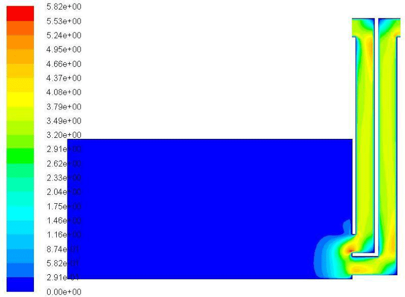
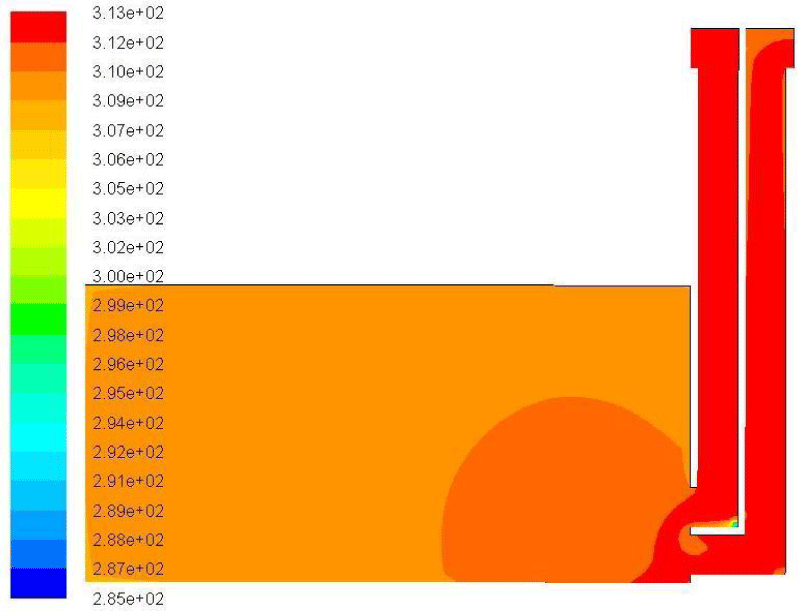
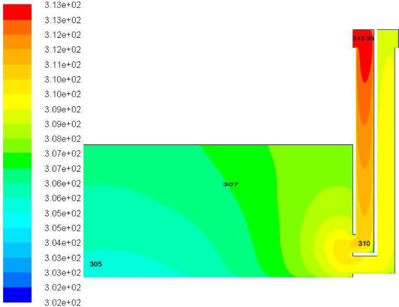
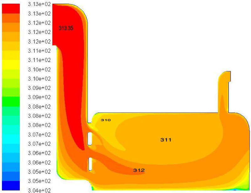
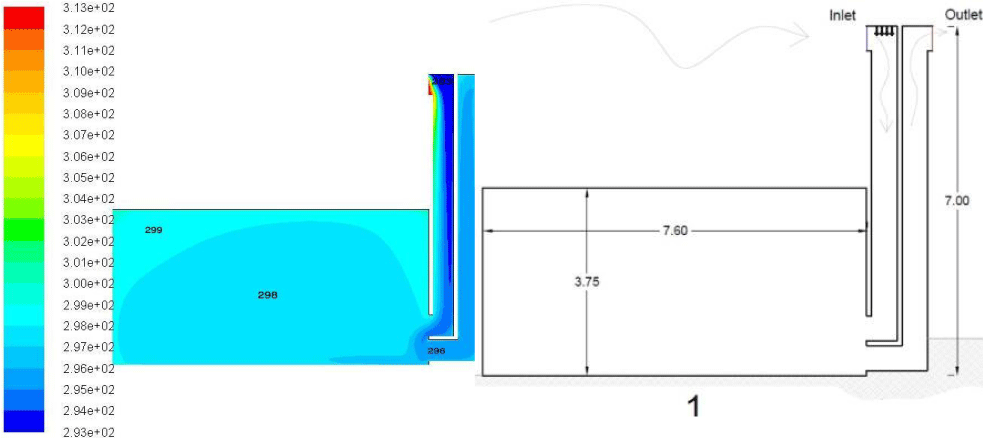
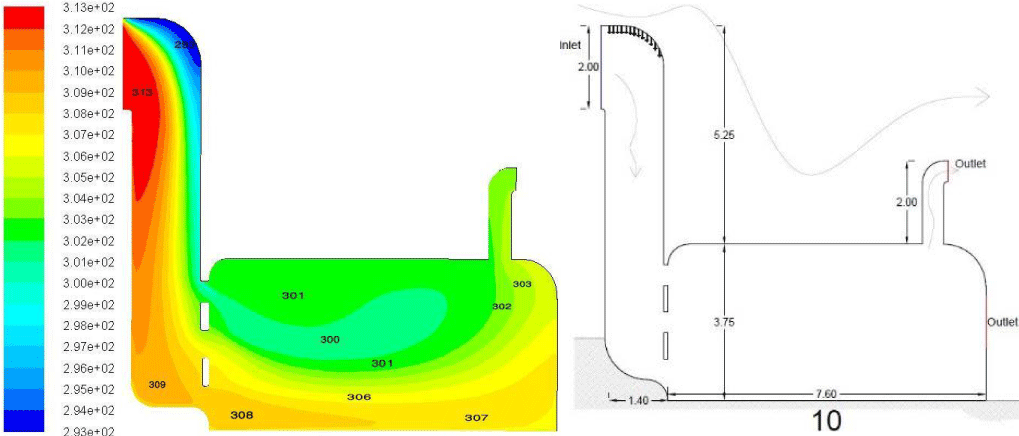
To temper the incoming air flow from the wind deflector into the settlement, one of these methods entails the placement of ponds there. A model of the room and wind deflector (brick) was created in Open Studio software to calculate the temperature of the air passing through it, and the surface temperature was obtained for the second day of July 4 at 4 p.m. in Kashan City with a maximum ambient air temperature of about 40.2° and wind flow at a speed of 3 meters per second (Figures 1-4).
Discussion about interior air temperature calculations (under the influence of moist surfaces)
After passing through the wind deflectors and striking the water’s surface in the pond, the airflow enters the settlement. This collision with the water results in heat exchange with the water in the pond and raises the relative humidity of the air, which cools the interior. According to the simulation’s findings, cooling the incoming airflow by rotating the environment lowers the temperature of the entire space.
The temperature contours show that by placing a horizontal moist surface at the lowest level of a wind deflector, we only see a 1 - 2degree decrease in the air temperature in the room, which is not a significant effect on evaporative cooling. The wind deflector greatly reduces the chance of creating a wind flow due to the buoyant force of the wind deflector column (Tables 5,6).
Investigating the effect of installing a fountain in the wind deflector
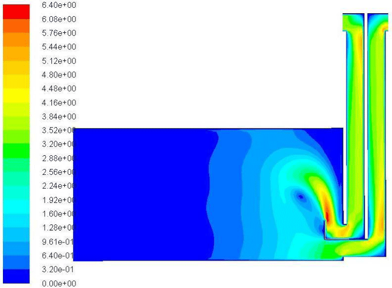
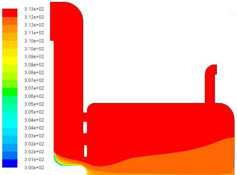
Installing a fountain and spraying water into the inlet air column of the air intake, which permits evaporative cooling of the room, is another type of solution to lower the temperature of the air input flow. The water fountain is situated such that it makes use of the buoyancy force at the top of the wind deflector column. We are aware that the quantity of heat removed from the air by the evaporation of water is what causes the heat exchange and decrease in air temperature. Then, to lower the temperature of the incoming wind flow, the water fountain installation in the wind deflector (combined model) 5 changes the amount of heat that the water droplets receive in exchange for the airflow. The results of putting the water fountain in the wind deflector are presented for the models (Table 4) modeled in (Figures 5,6).
The simulation results of wind deflectors with fountain installation
As stated in (Figures 5,6), the temperature in the wall of the drafty roof is higher than the room ceiling, and the temperature on the floor adjacent to the drafty soil is lower than the floor adjacent to the soil of the room. The temperature of the air entering the wind deflector has a temperature decrease of approximately 3 °C from the intake in the wind deflector type with a built-in basin. Due to the proximity of the room’s surfaces with differing temperatures, the air entering the room from the fan has a temperature decrease of roughly 3 to 4° (the temperature of the surfaces is obtained from Energy Plus software). The majority of the air volume in the room has a temperature reduction of 6 to 8° or 32°. which compared to its traditional model, i.e. the wind deflector with damp surfaces (2 degrees of temperature reduction), has a much greater temperature drop. Although, it is still far from the range of thermal comfort in Kashan. In model 10 (Figures 4,5) Wind deflectors with wetting surfaces, the air temperature in the room has a temperature drop of about 2.5 degrees. This wind deflector model has a temperature drop of less than 1 degree in its traditional model (moist surfaces). The enormous aperture of the wind deflector column, which allows a big volume of air with a temperature of more than 40° to enter the room, is the primary cause of the poor temperature reduction in this model. The air inside the wind deflector column of the model with the water fountain has a lower temperature than the surrounding space. Only the wind column experiences a temperature reduction of roughly 18°. A buoyancy force has been established by the spray at the wind deflector’s maximum elevation, and as hot air enters the device, it is immediately cooled by water at a temperature of 20°. In addition, when the ambient wind speed is low, it tends to drop in the wind column and produce a distinct flow, which may be extremely helpful. This is because of the rise in density. The air entering the room through the wind deflector is warmer than the air inside the wind deflector column at 4:00 p.m. on July 20. This is because the room’s air volume is greater than that of the wind deflector, and the room’s clay walls are warmer than the air inside the wind deflector. The temperature in the majority of the room is 25°, which is within Kashan’s 20.4 - 27° thermal comfort zone. The proportionality of dimensions, including those between the air input valve and the wind deflector, the temperature and flow of the water, the size and height of the wind deflector column, etc., is one of the primary causes of this temperature reduction. When employing wind deflector models with a big aperture and water fountain, the hot air outside affects the majority of the wind deflector column’s volume as a result of the wind deflector’s huge air entrance. The wind deflector’s lowest point results in a 4° reduction in temperature. The temperature of the chamber is 32.85 - 33.85 centigrade in the lower portion and near the floor and 26.85 - 27.85 centigrade in the higher portion. After being cooled by the geysers, the entering air slopes toward the bottom of the wind column, where it enters the chamber mostly when it reaches the first entrance valve. As a result, the temperature in the top half of the room is lower. Shortly thereafter, this heavier air moves to the bottom of the room, causing cold air to circulate within. With this type, the inside temperature drops by roughly 12° (Table 7).
Conclusion
By comparing the two analyses, we can infer that standard wind deflectors do not significantly lower temperatures and that ventilation in interior areas is only caused by the speed of the incoming wind. The following considerations are given by contrasting the outcomes of various applications for classic wind deflectors at the time of design. First, the airflow in the room is not well performed by the proximity of the wind deflector’s input and exit. Therefore, they ought to be separated from one another to create a better flow throughout the area. Second, high-speed flows cannot be produced by the short-height roof columns; instead, speeds that are higher than the ambient speed occur where the incoming flow experiences a 90° direction shift. Third, the maximum speed in the output column, which may be utilized as a location to install wind turbines for generating power, is caused by an increase in wind input columns with varying heights and an output column on the roof. In addition, the usage of a huge entry column impacts the air currents in the entire space, and designers might think about adding fans and tiny turbines on the windward surface inside the entry column. By adding a pond to the lowest level of a wind deflector, we can improve the effectiveness of the device and lower the temperature of the entering air, although the temperature drop in the room is only 1 to 2°. which again is not considered a significant effect in evaporative cooling The reduction in allowable inlet air temperature and room temperature caused by the installation of a fountain in a wind deflector suggests that it is preferable to use one with a fountain over a standard or pond wind deflector. The hot air entering the wind deflector is quickly cooled by the low-temperature water, and because of the increase in density, it tends to descend in the wind column and creates a separate flow from the ambient wind speed, especially in model 1. Because the spray is located at the highest elevation of the wind deflector, it creates a buoyancy force, wind deflectors with water fountains, the majority of the room is 25°, and it is situated in the thermal comfort range of Kashan city (20.4 - 27°), which may be extremely beneficial during the hours when the ambient wind speed is low. Additionally, based on the aforementioned findings, the primary factors influencing the temperature drop in the wind deflector, the proportionality of the air inlet’s dimensions to the wind deflector, the temperature of the water, and the dimensions and height of the wind deflector column can all be identified. The table below displays the amount of temperature reduction caused by evaporative cooling in various wind deflectors and demonstrates the stark contrast between classic and contemporary wind deflectors.
Author contributions
M. Karbasforoushha performed the literature review and model design, analyzed and interpreted the data, and prepared the manuscript text and edition. prepared the manuscript text and manuscript edition. Compiled the data and manuscript preparation
I want to thank the personnel of the Sciences Library of the Tehran Branch. Department of Architecture, Tehran-west Branch, Islamic Azad University, for helping us to gather the data and articles.
Conflict of interest
The authors declare no potential conflict of interest regarding the publication of this work. In addition, the ethical issues, including plagiarism, informed consent, misconduct, data fabrication, falsification, double publication and, or submission, and redundancy, have been completely witnessed by the authors.
- Mattoni BC, Guattari L, Evangelisti F, Bisegna P, Gori F, Asdrubali. Critical review and methodological approach to evaluate the differences among international green building rating tools, Renewable and Sustainable Energy Reviews. 2018; 82: 950-960; ISSN 1364-0321. https://doi.org/10.1016/j.rser.2017.09.105.
- Ramkishore Singh RL, Sawhney IJ, Lazarus VVN, Kishore. Recent advancements in earth air tunnel heat exchanger (EATHE) system for indoor thermal comfort application: A review, Renewable and Sustainable Energy Reviews. 2018; 82:3; 2162-2185: ISSN 1364-0321. https://doi.org/10.1016/j.rser.2017.08.058.
- KosutovaK, Hooff TV, VanderwelC, BlockenB, Hensen J. Cross-ventilation in a generic isolated building equipped with louvers: Wind-tunnel experiments and CFD simulations, Building and Environment. 2019; 154: 263-280; ISSN 0360-1323, https://doi.org/10.1016/j.buildenv.2019.03.019.
- Pan W, Liu S, Li S, Cheng X, Zhang H, Long Z, Zhang T, Chen Q. A model for calculating single-sided natural ventilation rate in an urban residential apartment, Building and Environment. 2019; 147:372-381; ISSN 0360-1323. https://doi.org/10.1016/j.buildenv.2018.08.047.
- Zomorodian ZS, Tahsildoost M, Hafezi M. Thermal comfort in educational buildings: A review article, Renewable and Sustainable Energy Reviews. 2016; 59:895-906; ISSN 1364-0321. https://doi.org/10.1016/j.rser.2016.01.033.
- Lau SSY, Zhang J, Tao Y. A comparative study of thermal comfort in learning spaces using three different ventilation strategies on a tropical university campus, Building and Environment. 2019; 148:579-599; ISSN 0360-1323. https://doi.org/10.1016/j.buildenv.2018.11.032.
- Wang B, Malkawi A. Design-based natural ventilation evaluation in early stage for high-performance buildings, Sustainable Cities and Society. 2019; 45:25-37; ISSN 2210-6707. https://doi.org/10.1016/j.scs.2018.11.024.
- Sadeghi H, Kalantar V. Performance analysis of a wind tower in combination with an underground channel, Sustainable Cities and Society. 2018; 37:427-437; ISSN 2210-6707. https://doi.org/10.1016/j.scs.2017.12.002.
- Chaudhry HN, Calautit JK, Hughes BR. Computational analysis of a wind tower assisted passive cooling technology for the built environment, Journal of Building Engineering. 2015; 1:63-71; ISSN 2352-7102. https://doi.org/10.1016/j.jobe.2015.03.004.
- Sadeghi M, Samali B, Wood G, Richard de Dear. Comfort cooling by wind towers in the Australian residential context - Experimental wind tunnel study of comfort, Journal of Wind Engineering and Industrial Aerodynamics. 2020; 196: 104014; ISSN 0167-6105. https://doi.org/10.1016/j.jweia.2019.104014.
- Dehghani-sanij AR, Soltani M, Raahemifar K. A new design of wind tower for passive ventilation in buildings to reduce energy consumption in windy regions, Renewable and Sustainable Energy Reviews. 2015; 42:182-195; ISSN 1364-0321. https://doi.org/10.1016/j.rser.2014.10.018.
- Ionescu C, Baracu T, Vlad GE, Necula H, Badea A. The historical evolution of the energy-efficient buildings, Renewable and Sustainable Energy Reviews. 2015; 49:243-253; ISSN 1364-0321. https://doi.org/10.1016/j.rser.2015.04.062.
- Calautit JK, Hughes BR, Nasir DSNM. Climatic analysis of a passive cooling technology for the built environment in hot countries, Applied Energy. 2017; 186:3; 321-335: ISSN 0306-2619. https://doi.org/10.1016/j.apenergy.2016.05.096.
- Reyes VA, Sierra-Espinosa FZ, Moya SL, Carrillo F. Flow field obtained by PIV technique for a scaled building-wind tower model in a wind tunnel, Energy and Buildings. 2015; 107:424-433; ISSN 0378-7788, https://doi.org/10.1016/j.enbuild.2015.08.047.
- Haghighi AP, Pakdel SH, Jafari A. A study of a wind catcher assisted adsorption cooling channel for natural cooling of a 2-storey building, Energy. 2016; 102:118-138; ISSN 0360-5442. https://doi.org/10.1016/j.energy.2016.02.033.
- Hughes BR, Calautit JK, Abdul SG. The development of commercial wind towers for natural ventilation: A review, Applied Energy. 2012; 92: 606-627:ISSN 0306-2619. https://doi.org/10.1016/j.apenergy.2011.11.066.
- Jomehzadeh F, Nejat P, John KC, Badruddin MMY, Sheikh AZ, Hughes BR, Yazid MNAWM. A review on windcatcher for passive cooling and natural ventilation in buildings, Part 1: Indoor air quality and thermal comfort assessment, Renewable and Sustainable Energy Reviews. 2017; 70: 736-756; ISSN 1364-0321. https://doi.org/10.1016/j.rser.2016.11.254.
- Farouk M. Comparative study of hexagon & square windcatchers using CFD simulations, Journal of Building Engineering. 2020; 31: 101366; ISSN 2352-7102. https://doi.org/10.1016/j.jobe.2020.101366.
- Montazeri H, Azizian R. Experimental study on natural ventilation performance of one-sided wind catcher, Building and Environment. 2008; 43: 2193-2202; ISSN 0360-1323. https://doi.org/10.1016/j.buildenv.2008.01.005.
- Mostafaeipour A, Bardel B, Mohammadi K, Sedaghat A, Dinpashoh Y. Economic evaluation for cooling and ventilation of medicine storage warehouses utilizing wind catchers, Renewable and Sustainable Energy Reviews. 2014; 38: 12-19; ISSN 1364-0321. https://doi.org/10.1016/j.rser.2014.05.087.
- Haw LC, Saadatian O, Sulaiman MY, Mat S, Sopian K. Empirical study of a wind-induced natural ventilation tower under hot and humid climatic conditions, Energy and Buildings. 2012; 52: 28-38; ISSN 0378-7788. https://doi.org/10.1016/j.enbuild.2012.05.016.
- Dehghan AA, Esfeh MK, Manshadi MD. Natural ventilation characteristics of one-sided wind catchers: experimental and analytical evaluation, Energy and Buildings. 2013; 61: 366-377; ISSN 0378-7788. https://doi.org/10.1016/j.enbuild.2013.02.048.
- Nejat P, John KC, Majid MZA, Hughes BR, Jomehzadeh F. Anti-short-circuit device: A new solution for short-circuiting in windcatcher and improvement of natural ventilation performance, Building and Environment. 2016; 105: 24-39; ISSN 0360-1323. https://doi.org/10.1016/j.buildenv.2016.05.023.
- Montazeri H. Experimental and numerical study on natural ventilation performance of various multi-opening wind catchers, Building and Environment, 2011; 46 Issue 2: 370-378; ISSN 0360-1323. https://doi.org/10.1016/j.buildenv.2010.07.031.
- Hosseinnia SM, Saffari H, Abdous MA. Effects of different internal designs of traditional wind towers on their thermal behavior, Energy and Buildings. 2013; 62: 51-58; ISSN 0378-7788. https://doi.org/10.1016/j.enbuild.2012.10.058.
- Salas MVC, Castillo JA, Huelsz G. Experimental study on natural ventilation of a room with a windward window and different wind exchangers, Energy and Buildings. 2014; 84: 458-465; ISSN 0378-7788. https://doi.org/10.1016/j.enbuild.2014.08.033.
- Montazeri H, Montazeri F. CFD simulation of cross-ventilation in buildings using rooftop wind-catchers: Impact of outlet openings, Renewable Energy. 2018; 118: 502-520; ISSN 0960-1481. https://doi.org/10.1016/j.renene.2017.11.032.
- Mehbobe PA, Hossein ASM. Classification of types of wind deflectors and spatial relationship with the summer area and corrective solutions, Shahr and Native Architecture Journal. 2011; 1(1): 7-18. https://civilica.com/doc/126628/
- Mahnaz M, Sidmjid MS. Wind deflector’s Iranian identity and its background in Iranian architecture. Urban Identity Magazine. 2008; 2(2): 25-33. https://www.sid.ir/fa/Journal/ViewPaper.aspx?ID=104663
- Mehdi B, Elah SH. Designing a building that does not require fossil energy in Tehran (Green building), Proceedings of the second fuel consumption optimization conference. 2002; 6-7: 1450-1472. Tehran.
- Mehdi B, Alireza D. Wind deflector, a masterpiece of Iranian engineering, Tehran, Yazda Publications. 2012. https://civilica.com/doc/2337
- Wali K. Simulation of ventilation and self-cooling of the building using the combination of solar wind and chimney (3D mode with the differential view), the first international conference on heating, cooling, and air conditioning, Tehran. 2009. https://civilica.com/doc/66698/
- Milad J, Reza ZA. The study of wind deflector structures and the optimization of the wind deflector section under the effect of renewable wind energy as an air conditioning system in old Iranian architecture. Two quarterly magazines of selected topics in energy. 2013. https://civilica.com/doc/529789/
- Ghadiri H, Lukman N. Wind Catcher, a Natural Evaporating Cooling System. Science and Humanities (IGCESH). 3rd International Graduate Conference on Engineering. School of Graduate Studies University Teknologi Malaysia. 2010.https://www.researchgate.net/publication/281774043
- Yaghoubi MA, Zamankhan P, Sabzevari A. Two-dimensional Numerical Simulation of Wind Flow and Ventilation in a Single Building Using the k-e Turbulent Model, Iranian Journal of Science and Technology.1998; 22(2): 81-97. https://www.jstor.org/stable/43749918
- Javad MM, Javanroudi C. Comparative comparison of the effect of airflow on two types of Yazdi and Kermani wind deflectors. Journal of Fine Arts.2011; 3(4): 69-80. https://jfaup.ut.ac.ir/article_29678.html
- Ali A. The solutions of traditional Iranian architecture in a hot and dry climate concerning natural ventilation and the use of its ideas in today's architecture, Master's thesis, University of Tehran, Tehran.2013. https://ut.ac.irfa/thesis
Article Alerts
Subscribe to our articles alerts and stay tuned.
 This work is licensed under a Creative Commons Attribution 4.0 International License.


 Save to Mendeley
