Journal of Civil Engineering and Environmental Sciences
Structural integrity of reinforced concrete slabs of some selected existing buildings based on field assessment
Akingbonmire Samuel Lambe*and Afolayan Joseph Olaseinde
Cite this as
Akingbonmire SL, Afolayan JO (2023) Structural integrity of reinforced concrete slabs of some selected existing buildings based on field assessment. J Civil Eng Environ Sci 9(2): 046-051. DOI: 10.17352/2455-488X.000067Copyright License
© 2023 Akingbonmire SL, et al. This is an open-access article distributed under the terms of the Creative Commons Attribution License, which permits unrestricted use, distribution, and reproduction in any medium, provided the original author and source are credited.Quality assurance and reinforcement detailing may affect the primary function of a reinforced concrete slab to transfer the load upon it by bending. This paper is focused on a probability-based approach to investigate the structural integrity of the reinforced concrete slabs of two selected buildings at a university campus. The in situ strength of all accessible floor slabs was measured using the Schmidt rebound hammer and Ultrasonic pulse velocity tester. The loadings on the slabs were analysed using Orion Software on the structural layouts of the two buildings. The integrity of the slabs, measured by their reliability indices, considering the yielding of the steel and deflection criteria, were estimated using the first-order reliability procedure. The computed indices were related to a target reliability index of 3.8 for the ultimate limit state and 1.5 for the serviceability limit state, chosen for a 50-years reference period of Class RC2 structural members according to BS EN 1990:2002+A1:2005. Generally, the safety indices decrease as the applied loads/moments increase for all the slabs in the two buildings. Although the estimated safety indices reveal that the slabs are over-designed, some of the slab panels in one of the buildings will fail the deflection criterion when loaded to about 80% of their ultimate capacity. Based on this assessment, a disparity in quality assurance between the two buildings has been established.
Introduction
Concrete, apart from being durable and easy to form to any desirable shape, is less expensive and can sustain bad weather [1]. It is also non-combustible and possesses high fatigue resistance [2]. Because of these properties, concrete is the most commonly used construction material [3-4]. It is used in buildings, storage tanks, bridges, pipelines, etc. Basically, concrete is composed of cement, aggregates (fine and coarse) and water, and sometimes admixtures [5]. It is very good in compression but poor in tension but to complement this, reinforcement, which is good in tension, is added to produce reinforced concrete [6]. In buildings, the structural elements include slabs, beams, columns, foundations, walls, and stairs [7]. Therefore, all the elements have one duty or the other in the functionality of the structure. These elements therefore need proper maintenance through conduction of structural integrity of the structural elements of the structure, in order to ascertain their level of fitness in service [8-12]. However, reinforced concrete slab, which is usually a flat horizontal surface, is used to form floors, walls, staircases, roofs, and foundations [13]. They are generally supported by beams, columns, walls, or the ground. Slabs, therefore, play a significant role in the stability of the building and comfort for users. In slab design, bending is usually considered in the ultimate limit state rather than shear; and deflection is majorly considered in the serviceability limit state [13]. Inadequate design of the slab may result in its failure and the parameters for the design are not deterministic but stochastic. The reliability prediction of the stochastic parameters with response to applied loading will shed light on the integrity of a building [14-16].
Literature review
Reliability analysis deals with the probability that a structure will not attain each specified limit state (ultimate or serviceability) during a specified reference period [17-19]. It deals with the rational treatment of uncertainties in structural engineering and with the methods for assessing the safety and serviceability of civil engineering structures and other structures. During a specific reference period, the safety of a structure is very important [20] as it depends on the magnitude of the load effect and the resistance of the structure. If the former is greater than the latter, the building is not safe. Therefore, the loads on a structure and resistance are uncertainties and therefore, are classified as random variables; and may be analysed by various reliability methods. Some of the methods are the First-Order Reliability Method (FORM) Second-Order Reliability Method (SORM), first-order second moment (FOSM), point estimate methods, Monte Carlo simulation methods, load and resistance factor design, and stochastic finite elements [21-24].
Structural analysis and design of irregularly shaped reinforced concrete slabs using a Simplified Design Method (SDM) was carried out [25] and discovered that the percentage difference of the simplified method with finite element software ranges from 4% to 12% and that the results obtained for all the selected irregular shaped slab sections indicated that the SDM was a good and quick approach to design irregular (triangular and curved) slab sections. Goutham and Manjunath [26] conducted research on reliability analysis of grid floor slabs as per IS456-2000 in limit state of flexure, shear, and deflection using the Monte Carlo simulation technique and Advanced First Order Second Moment (AFOSM) also known as Fisseler’s Algorithm method. It was observed that the reliability index varies from 3.23 to 5.16 for square grid slab in flexure; in shear, the reliability index varies from 4.90 to 5.83; and in deflection, the reliability index varies from 6.25 to 7.71. Also, the reliability index varies from 3.69 to 4.86 for rectangular grid slab in flexure; in shear, the reliability index varies from 4.83 to 5.84; and in deflection, the reliability index varies from 6.66 to 8.17. In this research work, FORM, from CalREL software [27], a coded algorithm, was used to estimate the reliability indices of accessible first-floor slabs of two University buildings. The results were compared with the targeted reliability index specified by [28].
Methodology
In order to carry out the reliability analysis of the panels of the slabs so as to predict their integrities, some performance functions are needed. They are:
Performance function of the ultimate moment of resistance of the slab
The limit state equation for this case is
g = Mult - Mapp (1)
where Mult is the ultimate moment and Mapp is the applied moment.
The limit state function for the failure of concrete in compression can be expressed as:
Where fcu is the characteristics strength of the concrete, b is the width of the section, d is the effective depth of the section, M is the applied moment, and α is the percentage of applied moment.
The statistics for the designed variables and the parameters in Equation (2) are summarised in Table 1.
Performance function for the deflection criterion for the slab
The deflection criterion for the deflection of the slab is given as:
Limiting span/Effective depth ≥ actual span/effective depth
Basic span/effective depth × modification factor ≥ actual span/effective depth;
According to [29], Table 1 (modification factor for tension reinforcement), the modification factor is given as:
Where fs is the estimated design service stress in the tension reinforcement; and
M is the design’s ultimate moment
The performance function for the deflection of the slab is
Basic span/effective depth ratio for simply supported beam = 20 (Table 2 [29]), therefore
The statistics of the variables and their assumed distribution types are shown in Table 2.
Generation of loadings for reliability analysis
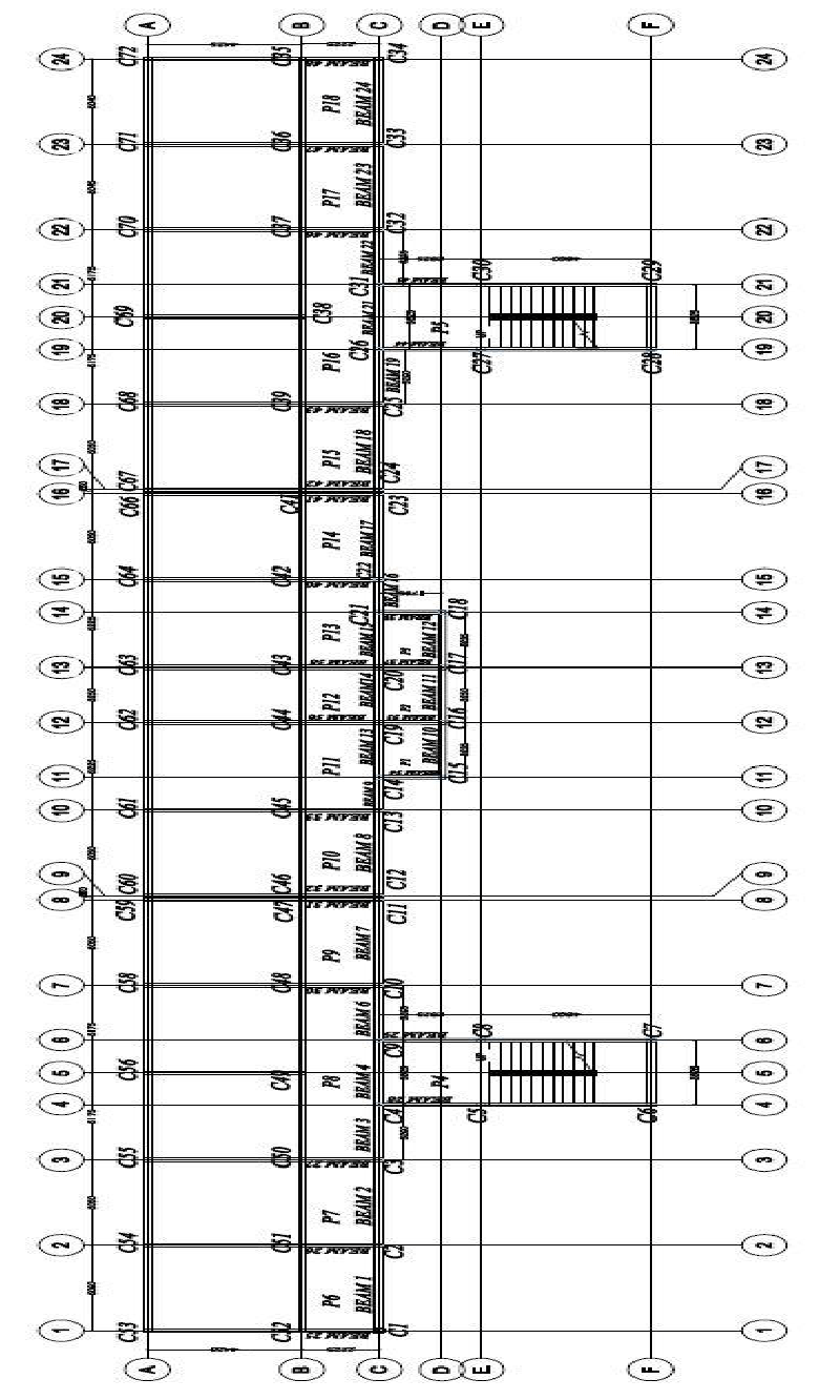
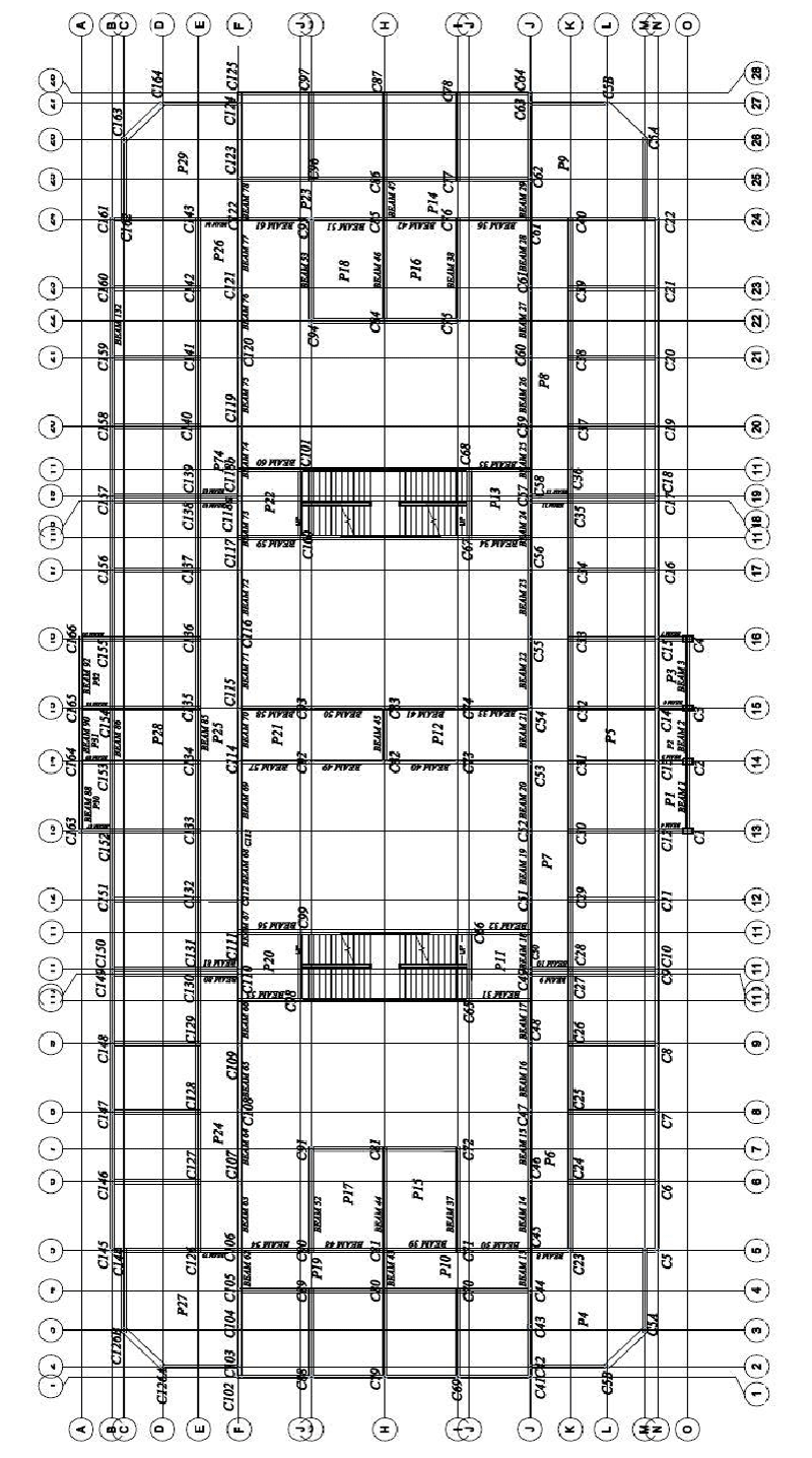
As can be seen in the structural layouts (Figures 1,2), building A has 18 accessible floor slab panels while building B has 32. The loadings on the panels of the slabs were generated using Orion Software [30] and were subjected to reliability analysis using CalREL software. The results of FORM were extracted for analysis.
Results and discussions
Reliability Indices of the slabs in the ultimate limit state for building A
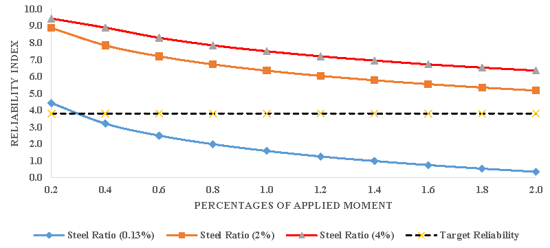
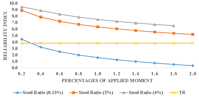
The trend of the plots of reliability indices against the probable accidental loadings (Figures 3,4) reveals that the safety indices decrease as the loadings increase on the slab for all the assumed steel ratios. A low steel ratio obviously results in a low-reliability level [31]. As stipulated in [29], the steel ratios range between 0.13%bh and 4%bh, where b and h are the width and depth of the section. The steel ratio of 2% and 4% produced safety indices that are far above the target safety level of 3.8 and the slab can survive the whole service life and will even sustain accidental load that is twice the designed applied load.
Reliability indices for the slabs in deflection for building A
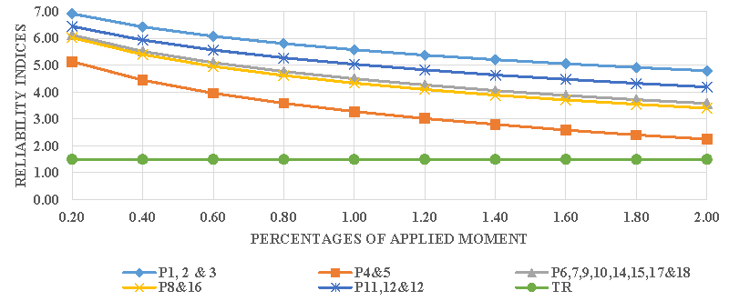
The effect of excessive deflection above the specified limit can never be overemphasized as the aftermath effects are undesirable. Apart from causing discomfort for the users, it also alters its aesthetics. Figure 5 shows that all the slab panels will not fail the serviceability limit state in deflection because their reliability indices are well above the target safety index, and the slabs can even carry almost twice their designed load throughout their service lives.
Reliability indices of the slabs in the ultimate limit state of building B
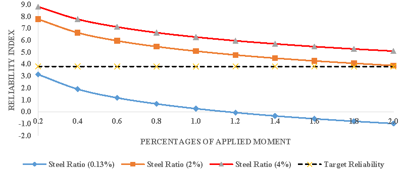
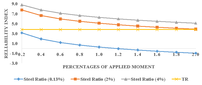
It is clear from Figures 6,7 that safety indices for slab panels in Building B follow a similar trend to those of Building A. For all the assumed steel ratios, the safety indices decrease as the loads increase. While the minimum steel ratio gives low safety indices, the steel ratios 2%bh and 4%bh produced very high safety indices well above the target safety level of 3.8.
Reliability indices for the slabs in deflection for building B
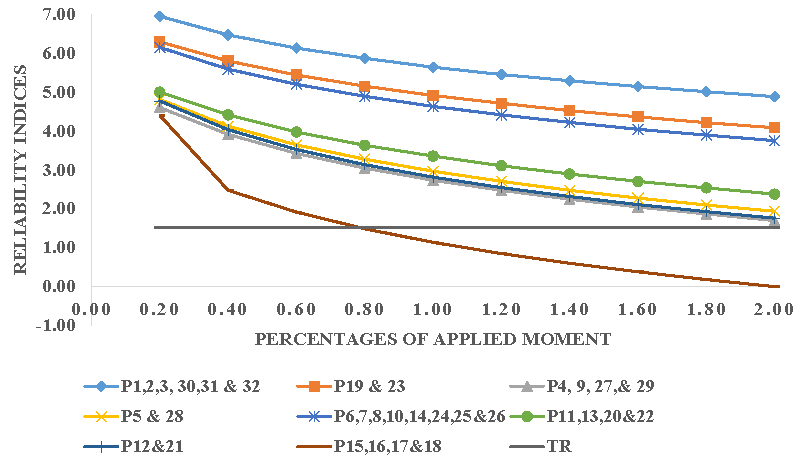
Of all the slab panels, panels 15, 16, 17, and 18 are critical because of their spans. Their reliability indices are very low when compared to the target safety level as shown in Figure 8. The slabs will be able to withstand only about 80% of the designed load in terms of the deflection criterion. Apparently, the slab will not accommodate the accidental load. Other slab panels have their safety indices well above the target safety level to the extent that when they are subjected to twice their designed loads, the serviceability limit state in deflection will not be violated.
Conclusion
Adverse effects of building collapse, make assessment of integrity of the structural elements of reinforced concrete structures very pertinent. The probability-based assessment of the slabs of the two University buildings shows that the slabs are well designed against the serviceability limit state of deflection except for a few panels that could only withstand not more than 80% of their designed loading to meet the target safety level. The slabs should be designed above the minimum steel ratio of 0.13%bh as their safety indices are below the targeted safety level of 3.8.
These findings indicate the fact that the buildings should undergo periodic structural monitoring checks in order to avoid progressive failure.
- Tantawi H. Introduction to Concrete Technology. 2015.
- ES380. Naval Material Science and Engineering (3-0-3). Chapter 14. https://www.usna.edu/NAOE/academics/en380.php.
- McGinley TJ, Choo BS. Reinforced Concrete: Design Theory and Examples, Second Edition, SPON Press, London, 1990.
- ProEst. The 5 Most Common Construction Materials. 2021. https://proest.com/construction/tips/common-materials/
- Arthur HN, David D, Charles WD. Design of Concrete Structures, Fourteenth Edition McGraw Hill, London, 2010.
- Mosley WH, Bungey JH. Reinforced Concrete Design, Fourth Edition, Macmillan, London.1990.
- Nadim MH, Akthem A. Structural Concrete: Theory and Design. Sixth Edition, John Willey and Sons, New Jersey, 2015.
- Alkali AM, Muhammad SI, Bulu K. Structural Integrity Assessment of an Uncompleted Reinforced Concrete Structure in Maiduguri, Nigeria. Arid Zone Journal of Engineering, Technology, and Environment. 2018; 14(3), 404 – 410.
- Salem MA, Abbas S, Nehdi ML. Assessment of Reinforced Concrete Slabs Using In-situ Load Testing: A Case Study. Journal of Building Engineering. 2019; 25. https://doi.org/10.1016/j.jobe.2019.100844.
- Akingbonmire SL, Afolayan JO, Olanitori LM, Ikumapayi CM. Quality Assessment of Reinforced Concrete Structural Elements of Some Selected University Buildings Using Ultrasonic Pulse Velocity Test. Journal of Multidisciplinary Engineering Science Studies. 2021; 7(12). 4162-4169.
- Akingbonmire SL. Assessment of Concrete Quality of Reinforced Concrete Structural Elements of University Buildings Using Schmidt Hammer. ANNALS of Faculty Engineering Hunedoara – International Journal of Engineering. 2022; 20(2):89-96.
- Atoyebi OD, Afolayan JO, Arum C, Alabi SA. Statistical Analysis of Rebound Hammer Assessment on Reinforced Concrete Buildings. International Conference on Science, Engineering, and Business for Sustainable Development Goals (SEB-SDG), Omu-Aran, Nigeria. 2023; 1-10. Doi: 10.1109/SEB-SDG57117.2023.10124607.
- Chanakya A. Design of Structural Elements: Concrete, Steelwork, Masonry and Timber Designs to British Standards and Eurocodes. Third edition, Son Press, London. 2009.
- Alabi SA. Reliability-based Appraisal of Existing Reinforced Concrete Building. The Seventh Asian-Pacific Symposium on Structural Reliability and Its Applications. 2020; T Takada, I Yoshida, T Itoi (editors).
- Aladegboye OJ, Opeyemi DA, Atoyebi1 OD, Akingbonmire SL, Ibitogbe EM. Reliability analysis of reinforced concrete beam using varying properties. IOP Conference Series: Earth and Environmental Science. 2020; 445, 012031. DOI 10.1088/1755-1315/445/1/012031.
- Abdulhakim AS, Ali M, Peyman A, Phil H, Athanasios K. Sensitivity analysis of design parameters for reliability assessment of offshore wind turbine jacket support structures. International Journal of Naval Architecture and Ocean Engineering. 2022; 12:100441. https://doi.org/10.1016/j.ijnaoe.2022.100441
- Palle TC, Michael J. Structural Reliability Theory and its Applications. Springer-Verlag Berlin Heidelberg, New York. 1982.
- Quadri AI. Reliability Appraisal of Nominal Eccentricity of Short Reinforced Concrete Column Designed to BS 8110 and Eurocode (EN: 2) - Ultimate Limit State on Fatigue. Reliability Engineering and Resilience. 2019; 1-2, 01-14.
- Prasad PH, Devi TS, Maheswari SU. Reliability Analysis of Structural Beam Section Using First Order Reliability Method (FORM). International Journal of Scientific Research in Science and Technology.2018; 4(5): 641- 648.
- Ranganathan R. Structural Reliability Analysis and Design. Second Edition, Jaico, Mumbai, 2000.
- Baecher GB, Christian JT. Reliability and Statistics in Geotechnical Engineering. John Wiley and Sons, England, 2003.
- Abejide OS. Reliability analysis of Bending, Shear, and Deflection criteria of reinforced concrete slabs. Nigerian Journal of Technology. 2014; 33(3):394-400.
- Opaleye OA, Quadri AI. Cal-Reliability Assessment of Failure of Industrial Structural Steel Roof Truss Systems. Software Engineering. 2018; 6(1):12-19.
- Akingbonmire SL. Probabilistic Assessment of Structural Integrity of Reinforced Concrete Rectangular Beams Based on Material Failure. American Journal of Engineering Research. 2022; 11(6): 229-240.
- Mohammed SA, Muhammad SA. Structural analysis and design of irregularly shaped reinforced concrete slabs using a simplified design method. Journal of Structural Engineering and Applied Mechanics. 2020; 3(4):276-288.
- Goutham DR, Manjunath K. Reliability Analysis of Grid Floor Slabs. International Research Journal of Engineering and Technology. 2016; 3(6):1876-1882.
- Pei-Ling L, Hong-Zong L, Armen DK. CalREL User Manual, Structural Engineering, Mechanics, and Materials, Department of Civil Engineering, University of California, Berkeley. 1992.
- BS EN 1990:2002+A1:2005. Eurocode – Basis of Structural Design.
- BS 8110-1:1997. Structural use of concrete – Code of practice and construction
- Orion Software. CSC Ltd, UK. 2013.
- Olusola JA, Opeyemi EO. Olaseinde JA. Reliability Assessment of BS 8110 (1997) Ultimate Limit State Design Requirements for Reinforced Concrete Columns. Jordan Journal of Civil Engineering. 2017; 11(3):512-524.
Article Alerts
Subscribe to our articles alerts and stay tuned.
 This work is licensed under a Creative Commons Attribution 4.0 International License.


 Save to Mendeley
