Journal of Civil Engineering and Environmental Sciences
Model analysis of electroflotation water treatment of wastewater containing microplastics
Ksenofontov Boris Semenovich*, Bondarenko Anna Viktorovna and Rusanova Kristina Rodionovna
Cite this as
Semenovich KB, Viktorovna BA, Rodionovna RK (2023) Model analysis of electroflotation water treatment of wastewater containing microplastics. J Civil Eng Environ Sci 9(1): 014-019. DOI: 10.17352/2455-488X.000062Copyright License
© 2023 Semenovich KB, et al. This is an open-access article distributed under the terms of the Creative Commons Attribution License, which permits unrestricted use, distribution, and reproduction in any medium, provided the original author and source are credited.The paper presents a model of the microplastic electroflotation process and considers the factors affecting the efficiency of this process during wastewater treatment. The results obtained will help optimize the microplastic electroflotation process and develop more effective ways to remove plastic particles from the treated water, as well as help in the development of new types of flotation technology that allow several purification processes to be carried out simultaneously in one device. These devices can prevent the destruction of the formed flotation complexes, compared with the use of a traditional cleaning scheme with several autonomous devices installed in series. The results obtained provide a rationale for choosing the most efficient electroflotation apparatus for wastewater treatment from microplastics.
Introduction
Microplastics (tiny plastic particles less than 5 mm in size) have become a global environmental problem due to their widespread presence in the environment and potentially harmful effects on marine organisms and ecosystems. One of the main sources of microplastics is wastewater, which contains a significant amount of it and enters natural water bodies (rivers, lakes, oceans), disrupting their ecosystems. Thus, the development of effective methods for the removal of microplastics from wastewater is important for the preservation of the health of aquatic ecosystems.
Let’s consider one of the effective ways to remove microplastics from wastewater - flotation. This process involves attaching polluting particles to air bubbles that rise to the surface of the water and can be mechanically removed. However, the effectiveness of microplastic flotation depends on various factors, such as the properties of the microplastic, the chemical composition of the water and the flotation conditions.
In this research paper, we aim to simulate the process of microplastic flotation using electrolysis production of gas bubbles and to investigate the factors affecting its effectiveness. Our results can help optimize the microplastic electroflotation process and develop more effective methods for its removal from wastewater. This is extremely important since the growing use of plastics worldwide has led to the appearance of an alarming amount of microplastics in the environment [1,2]. For example, in the study [3] it is estimated that the oceans alone contain more than 5 trillion microplastic particles. Another study showed that wastewater after treatment facilities can emit up to 4.2 million microplastic particles into the environment per day [4]. The data obtained as a result of the literature review emphasize the need to solve the problem of microplastic pollution of water bodies [5].
Research of a multi-stage model
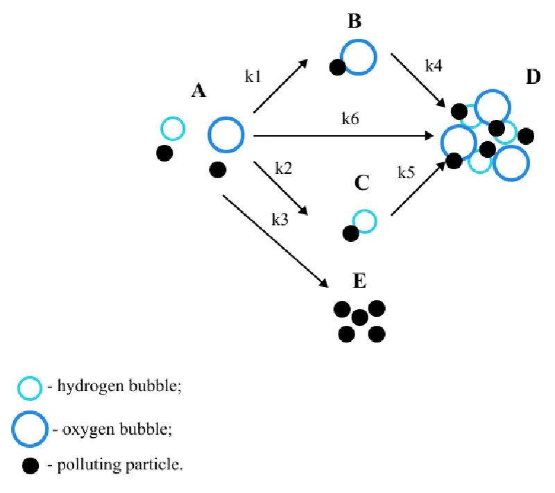
This paper considers B.S. Ksenofontov’s multi-stage model [6-9] of the electroflotation process. The model is presented in Figure 1. Glitter consisting of small plastic particles was chosen as polluting particles, the peculiarities of the material’s behavior in water were taken into account and two different types of bubbles arising during electroflotation were considered [10-12]: hydrogen bubbles and oxygen bubbles [13,14].
In the considered model, state A is the initial state of the system; B and C are the states of adhesion of particles to bubbles; E is the precipitation of particles; D is the state of particles in the foam layer.
The process can be described by a system of differential equations:
Where CA, CB, CC, CD, CE – particle concentrations in states А, B, C, D, and E; state А – polluting particles in their original form, В – flotation complexes with oxygen bubbles, С – flotation complexes with hydrogen bubbles, E represents the state of precipitated particles, D is the state of particles in the foam layer; k1 coefficient describes the probability of formation of the “polluting particle –oxygen bubble” flotation complex, k2 is the probability of the formation of a “polluting particle – hydrogen bubble” flotation complex, k3 is the probability of precipitation of a particle from state A; k4 coefficient characterizes the rising process of the flotation complex “particle–oxygen bubble”, k5 characterizes the rising process of the flotation complex “particle–hydrogen bubble”, k6 represents the probability of the particle passing directly into the foam layer.
Initial conditions for this system of equations at t = 0:
The system of equations (1) was solved in the Mathcad software package.
The probability of the formation of a flotation complex is determined by the constants k1,2, which can be calculated using the formulas [15,16]:
Where k3 is the electrochemical equivalent of the substance, kg/C;
j is current density, A/m2;
E is the efficiency of particle capture by a gas bubble during flotation, (DN);
K0 is bubbles polydispersity factor, (DN);
, are mean diameters of the bubbles in the flotation cell, m;
ρ is gas density, kg/m3;
q is the bubbling rate, m3/(m2 . s).
Sedimentation of microplastic particles is represented in k3 coefficient. To determine the coefficient, an experiment was conducted to observe the deposition of microplastic particles. k3 the coefficient is determined by the formula:
Where vsed is sedimentation velocity of a microplastic particle, m/s;
H is the depth of the flotation chamber, m.
Sedimentation velocity is determined by the formula:
Where S is the distance traveled by a microplastic particle, m;
t is the time it took for the particle to travel the distance S, s.
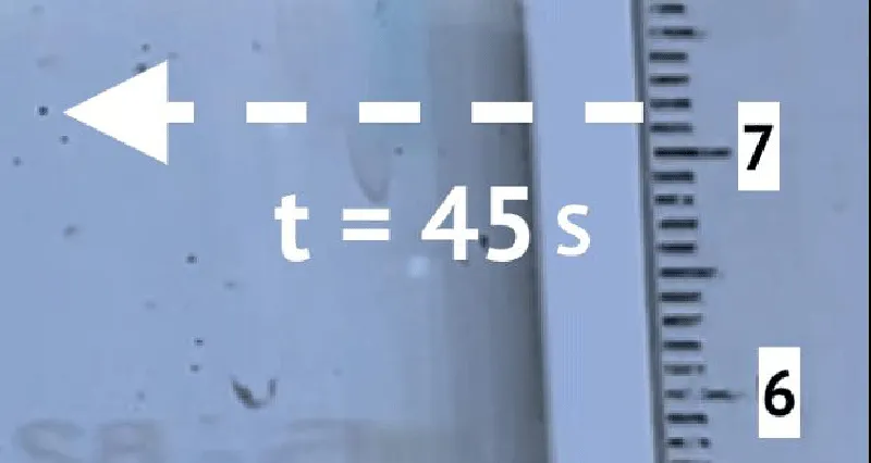
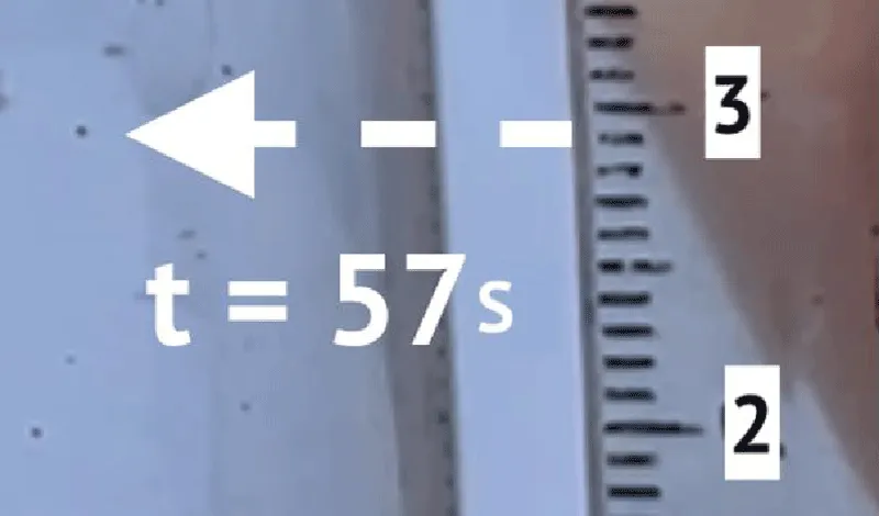
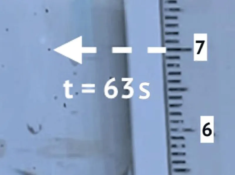
To determine the sedimentation velocity, 10 microplastic particles were observed. Figures 2 and 3 show an example of observation. Table 1 shows the results of observations.
Figures 2 and 3 show an example of a precipitating particle. Table 1 shows the results of observations. According to the results of the experiment, the coefficient k3 = 0,0036 s-1 .
The rise of the flotation complexes is characterized by coefficients k4,5, which can be calculated by the formula:
Where vr4,5 is rise velocity of flotation complex, m/s;
H is the depth of the flotation chamber, m.
The transition of the polluting particle into the foam layer is characterized by the k6 coefficient, which is calculated by the formula:
Where vf is the velocity of self-ascent of a microplastic particle, m/s;
H is the depth of the flotation chamber, m.
The determination of the coefficient k6 according to the formula (8) by the formula (8) is possible if the density of the microplastic is less than the density of water. Since part of the microplastics rose to the surface during the experiment, this assumption was accepted. The particle self-ascent velocity is determined similarly to the sedimentation velocity.
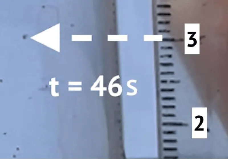
To determine the self-ascent velocity and the coefficient k6 10 microplastic particles were observed. Figure 4 shows the initial state of the particle, Figure 5 shows the final state.
The results of the experiment are presented in Table 2. According to the results of the experiment, the value of the coefficient k6 is 0,0025 s-1.
The efficiency of particle capture by gas bubbles is determined by the formula [11]:
Where rų is particle radius, m;
γn is bubble radius, m;
A is the Hamaker constant, J.
In addition to electroflotation, the model takes into account the presence of Al(OH)3 coagulant. The value of the Hamaker constant for this case is given in Table 3.
The rise velocity of the flotation complex is determined by the formula [15]:
Where is the mean diameter of the bubbles in the flotation cell, m;
ρw is water density, kg/m3;
ρg is gas density, kg/m3;
µ is water viscosity, kg/m·s.
Thus, the presented multi-stage flotation model allows us to consider the influence of various parameters on the efficiency of the process, such as the size of bubbles (depending on the nature of the flotation process), current density, and bubbling rate. In addition, the multi-stage model takes into account various options for the location of pollution particles during the water treatment process.
Calculation of flotation time
For the calculation and graphical representation of the model, a similar process was carried out for the purification of oily wastewater [17,18]. The calculation was made using the initial data presented in Table 3. Reference data is taken from [15,16,18-66].
The parameters calculated by formulas (9), and (10) are presented in Table 4. The obtained values of the constants are presented in Table 5.
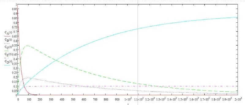
The solution of the system of differential equations in graphical form is shown in Figure 6.
Using the graphical solution, the flotation time was determined. To achieve a degree of purification of 80%, the required flotation time is 1900 seconds.
Conclusion
From the presented flotation process model, it can be concluded that despite the ability of microplastics to independently rise into the foam layer and precipitate other features of the material slow down the flotation time.
Thus, it is necessary to provide additional stages of finer purification, but the use of electroflotation with the ability to adjust the size of bubbles can significantly reduce the concentration of microplastics in water. In the future, the model will be tested experimentally and refined to obtain the final results.
The results obtained in this work provide a rationale for choosing the most efficient electroflotation apparatus for wastewater treatment from microplastics.
- State Report "On the state and environmental protection of the Russian Federation in 2020". Moscow: Ministry of Natural Resources of Russia; Lomonosov Moscow State University. 2021; 864.
- State report "On the state and environmental protection of the Russian Federation in 2021." Moscow: Ministry of Natural Resources of Russia; Lomonosov Moscow State University. 2022; 684.
- Eriksen M, Lebreton LC, Carson HS, Thiel M, Moore CJ, Borerro JC, Galgani F, Ryan PG, Reisser J. Plastic Pollution in the World's Oceans: More than 5 Trillion Plastic Pieces Weighing over 250,000 Tons Afloat at Sea. PLoS One. 2014 Dec 10;9(12):e111913. doi: 10.1371/journal.pone.0111913. PMID: 25494041; PMCID: PMC4262196.
- Murphy F, Ewins C, Carbonnier F, Quinn B. Wastewater Treatment Works (WwTW) as a Source of Microplastics in the Aquatic Environment. Environ Sci Technol. 2016 Jun 7;50(11):5800-8. doi: 10.1021/acs.est.5b05416. Epub 2016 May 18. PMID: 27191224.
- Emamjomeh M, Kakavand S, Jamali H, Alizadeh SM, Safdari M, Mousavi SES, Hashim KS, Mousazadeh M. The treatment of printing and packaging wastewater by electrocoagulation-flotation: the simultaneous efficacy of critical parameters and economics. Desalination and Water Treatment. 2020; 205:161-174. DOI: 10.5004/dwt.2020.26339
- Yu S, Andreev BM, Grishin IB, Shirshin AM, Khromova. Mathematical modeling of flotation wastewater treatment processes // Tr. International. symposium "Reliability and Quality". 2009; 2.
- Comninellis С. Electrochemistry for the Environment. 2010th edition / Comninellis C, Chen G. 2009; 575.
- Chen X, Chen G. Electroflotation // Electrochemistry for the Environment. 2010; 263-277.
- Gmurman VE. Probability theory and mathematical statistics: textbook for universities. Moscow. Higher School. 2003; 479.
- Gaidukova AM, Brodsky VA, Kolesnikov VA. The influence of the pH of the medium on the physicochemical characteristics and efficiency of electroflotation extraction of poorly soluble cerium (III, IV) compounds from aqueous solutions // Journal of Applied Chemistry. 2015; 88:9; 1300.
- Ksenofontov BS, Antonova ES, Bondarenko AV, Kapitonova SN. Theoretical foundations of the electroflotation method of wastewater treatment and their experimental confirmation // Water treatment. 2014; 8:14-25.
- Lafrance P, Grasso D. Trajectory modeling of non-brownian particle flotation using an extended derjaguin-landau-verwey-overbeek approach. Environ Sci Technol. 1995 May 1;29(5):1346-52. doi: 10.1021/es00005a029. PMID: 22192031.
- Andraos JA. A streamlined approach to solving simple and complex kinetic systems analytically // Journal of Chemical Education. 1999; 76:11; 578 1583.
- Bondarenko AV. Intensification of the electroflotation method of purification of oil-containing wastewater of energy enterprises, Candidate of Technical Sciences: Moscow. 2022; 139.
- Ksenofontov BS. The use of a multi-stage flotation model and the development of KBS-type flotation combines for water purification / BS Ksenofontov. Moscow: Bauman Moscow State Technical University. 2019; 156.
- Ksenofontov BS, Antonova ES, Bondarenko AV. Modeling of wastewater treatment by electroflotation // Ecology of industrial production. 2015; 1(89):36-40.
- Ben L. Mansour S. Chalbi, Kesentini I. Experimental study of hydrodynamic and bubble size distributions in electroflotation process. Indian Journal of chemical technology. 2007; 14:3; 253257.
- Ksenofontov BS, Rusanova KR. Possibilities of using electroflotation combine for wastewater treatment // Ecology of industrial production. 2022; 3(119):13-17.
- Rojas H, Ronald, Merma, Antonio, Hudson, Torem C, ML. Measurement and analysis of H2 and O2 bubbles diameter produced by electroflotation processes in a modified Partridge-Smith cell // Powder Technology. 2018; 342.
- Antonova ES, Sazonov DV. Improving the efficiency of water purification in pneumohydraulic flotation plants // Water and ecology: problems and solutions. 2019; 1:3-9.
- Bondarenko AV, Ksenofontov BS. Multistage model of the electroflotation method of wastewater treatment // Collection of reports of the Twelfth All-Russian Conference of Young Scientists and Specialists (with international participation) "The Future of Russian Engineering". Moscow: Bauman Moscow State Technical University (National Research University). 2019; 605-609.
- Ksenofontov BS. Natural Environment Safety: Biotechnical Bases. М.: Publishing House «Forum»: INFRA-М. 2016; 200.
- Ksenofontov BS. Treatment of Wastewater Sediments. М.: INFRA-М. 2019; 262.
- Ksenofontov BS. Wastewater Purification Intensification by Flotation. Saarbrücken: LAP LAMBERT. 2012; 99.
- Ksenofontov BS. Water Systems Flotation Treatment. Saarbrücken. LAP LAMBERT. 2011; 189.
- Kolesnikov VA, Ilyin VI, Kapustin YuI, Varaksin SO, Kisilenko PN, Kokarev GA. Electroflotation Technology for Purification of Wastewater of Industrial Enterprises / Editor Kolesnikov VAМ. Chemistry. 2007; 303.
- Bondareva GM. Development of Flotation Process of Extraction of Surfactants and Motor Fuels from Water Drainages: Dissertation for Ph.D. in Chemistry: Moscow. 2010; 174.
- Nazarov MV, Vineshtock PN, Voronina AN. Preparation of Under-Commodity Waters for Low-Permeability Collectors of Oil by Electroflotation Method // Oil and Gas Business: Scientific Electronic Journal. 2014; 12014.
- RF Patent on Innovation No. 2108974 «Way of Wastewater Purification», accepted 04/22/1996, registered 04/20/1998. Author and Applier Ksenofontov BS.
- Ksenofontov BS, Senik EV. Cleaning of Wastewaters on Flotation Decanters. Life Safety. 2018; 5(209): 21–26
- Golman AM. Ionic Flotation. М. Subsoils. 1982; 143.
- Ksenofontov BS. Wastewater Flotation Purification. М.: New Technologies. 2003; 160.
- Ksenofontov BS. Multistage Model of Flotation and Flotoharvesters: Monography. Tver: Tver State University. 2019; 194
- RF Patent on Useful Model No. 183320. Ejector-Mixer accepted 07/16/2018, registered 09/18/2018. Author and Applier Ksenofontov B.S. (in Russian).
- Ksenofontov BS. Wastewater Purification: Flotation Kinetics and Flotation Harvesters. М: PH: Forum: INFRA-М. 2015; 256.
- Ksenofontov BS, Kapitonova CN, Senik EV. The Usage of Ksenofontov’s Multistage Model in the Processes of Flotation Purification of Wastewaters: Monograph Тver: Tver State University, 2019; 162.
- RF Patent on Useful Model No. 170182. Flotation Harvester for Wastewater Purification accepted 07/25/2016, registered 04/18/2017. Author and Applier Ksenofontov B.S. (in Russian).
- RF Patent No. 2658411. Flotation Harvester for Wastewater Purification, accepted 04/11/2017, registered 06/21/2018. Author and Applier Ksenofontov B.S. (in Russian).
- RF Patent No. 2669842. Flotation Harvester for Wastewater Purification, accepted 11/17/2017, registered 10/16/2018. Author and Applier Ksenofontov B.S. (in Russian).
- Ksenofontov BS. Wastewater Purification in Flotation Columns. Water Purification. 2018; 18–23. (in Russian).
- Ksenofontov BS. Mathematical Models of Complex Articulated Processes in Flotation Harvesters for Wastewater Purification. Water Purification. 2018; 7-11.
- Ksenofontov BS. Industrial Wastewater Purification from Mineral Oils by Flotation with Out-Extraction of Micro-flotocomplexes. Water Purification. 2018; 12-18.
- Ksenofontov BS. Intensification of Wastewater Purification with the Use of Combined Flotation Technique. Water Purification 2018, 8-13.
- Ksenofontov BS. Models of Complex Flotation Processes of Wastewater Purification. Water Purification. 2018; 59–69.
- Ksenofontov BS. Wastewater Purification: Multistage Flotation Model and Flotoharvesters. Water Purification. 2018; 12; 5-21.
- Ksenofontov BS. Wastewater Purification with the Use of Ionic Flotation. Water Purification. 2018; 5-15.
- Ksenofontov BS, Stelmach ES. Ejectors qua Mixers for Reagent Treatment of Water. Water Purification. 2018; 70–74.
- Ksenofontov BS, Stelmach ES. Intensification of Wastewater Flotation Purification with the Use of Jet Aerators and Ejectors. Water Purification. 2018; 25-35.
- Ksenofontov BS. Possibilities of Usage of Pressure-head Flotation Skimmers for Thickening and Inactivation of Active Silt Biomass. Water Purification. 2018, 14–19 (in Russian).
- Ksenofontov BS, Kozodaev AS. Flotation Method of Active Silt Thickening with the Use of Carbon Dioxide. Dulina L.A. 7th International Congress Water: Ecology and Technology (EQUATEC-2006). 2006; 2: 830.
- Ksenofontov BS. Water Preparation and Water Offtake. М.: Publishing House «Forum» — INFRA-М. 2018; 298.
- Ksenofontov BS, Titov K. Multistage Ksenofontov Model of Flotation und uts. Saarbrucken: LAP LAMBERT Acad. Publ. 2019; 57.
- Ksenofontov BS. Wastewater Purification: Multistage Flotation Model and Flotation Harvesters. Water Purification. 2018; 12: 5-21.
- Ksenofontov BS. Generalized Multistage Flotation Model and Development of Flotoharvesters of KBS Type and of Special Purpose for Purification of Water and Soil: Monograph. Tver State University. 2019; 104.
- Ksenofontov BS. Multistage Model of Flotation Process for Water Purification. IOP Conference Series: Materials Science and Engineering. 2019; 492: 012033. DOI: 10. 1088/1757 -899Х/492/1/012033.
- Ksenofontov BS. Simulation of Wastewater Treatment in Flotation Machine. AIP Conference Proceedings. 2019. 2195: 020070. DOI: 10. 1063/1.5140170.
- Ksenofontov BS, Sazonov DV. RF Patent on Useful Model 123 001. Flotation Machine for Wastewater Purification accepted 07/24/12, registered 12/20/12. Applier: Bauman State Technical University.
- Ksenofontov BS, Petrova EV, Vinogradova MS. RF Patent on Useful Model 143 014. Flotation Machine for Wastewater Purification accepted 12/30/13, registered 07/10/14. Applier: Bauman State Technical University.
- Ksenofontov BS, Antonova ES. RF Patent on Useful Model No. 149273. Flotation Machine for Wastewater Purification.
- Ksenofontov BS. RF Patent on Useful Model No. 192973 “Bioflotoharvester”, taken 06/18/2019, registered 10/08/2019.
- Ksenofontov BS. RF Patent on Useful Model No. 194987 “Chemoflotoharvester”, taken 08/09/2019, registered 01/10/2020.
- Ksenofontov BS. RF Patent on Useful Model No. 194985 “Electroflotoharvester”, taken 08/22/2019, registered 01/10/2020.
- Ksenofontov BS. RF Patent on Useful Model No. 194986 “Deminoflotoharvester”, taken 09/16/2019, registered 01/10/2020.
- Ksenofontov BS. RF Patent on Useful Model No. 195481 “Silt-flotoharvester”, taken 10/25/2019, registered 01/29/2020.
- Ksenofontov BS. RF Patent on Useful Model No. 195504 “Soil-flotoharvester”, taken 11/05/2019, registered 01/29/2020.
- Ksenofontov BS. RF Patent on Useful Model No. 199049 Aquaflotoharvester, accepted 02/05/2020, registered 08/11/2020.
Article Alerts
Subscribe to our articles alerts and stay tuned.
 This work is licensed under a Creative Commons Attribution 4.0 International License.


 Save to Mendeley
