Journal of Civil Engineering and Environmental Sciences
BIM methodology implementation in structural design: Adaptation of procedures and information management
Gonçalo Ferreira Azevedo*
Cite this as
Azevedo GF (2022) BIM methodology implementation in structural design: Adaptation of procedures and information management. J Civil Eng Environ Sci 8(2): 093-099. DOI: 10.17352/2455-488X.000058Copyright License
© 2022 Azevedo GF. This is an open-access article distributed under the terms of the Creative Commons Attribution License, which permits unrestricted use, distribution, and reproduction in any medium, provided the original author and source are credited.Building Information Modelling (BIM) is a methodology that accompanies technological evolution and consists of a set of processes and tools that allows the creation of a three-dimensional digital model. This model centralizes information, facilitating its access and exchange between the entities along the life cycle of a building.
This study focuses on the application of BIM methodology within the framework of a structural design, identifying the benefits and limitations that it provides and indicating strategies that may be used to improve the quality of a project. A structural model was created through BIM-based platforms and then transferred to the calculation software where the structural analysis and design were carried out. After this, through the conceived digital model, various applications that it allows were explored, namely, the method of coordination and collaboration, detection of conflicts, production of drawings, the budget, and an immediate evaluation of the environmental impact of the structure
This study demonstrates a significant improvement in the quality of the structural design. Therefore, even though some limitations still exist, the implementation of this methodology is essential to improve the process in the AEC sector.
Introduction
One of the main objectives of the architecture, engineering, and construction (AEC) industry is the constant need to produce more efficient workflows, contributing to increasing the quality of the final product and reducing cost. To achieve this, the use of new technologies, which have been introduced in the sector is inevitable, in order to facilitate communication and avoid repetitive and exhaustive tasks that cause inconsistencies and productivity loss.
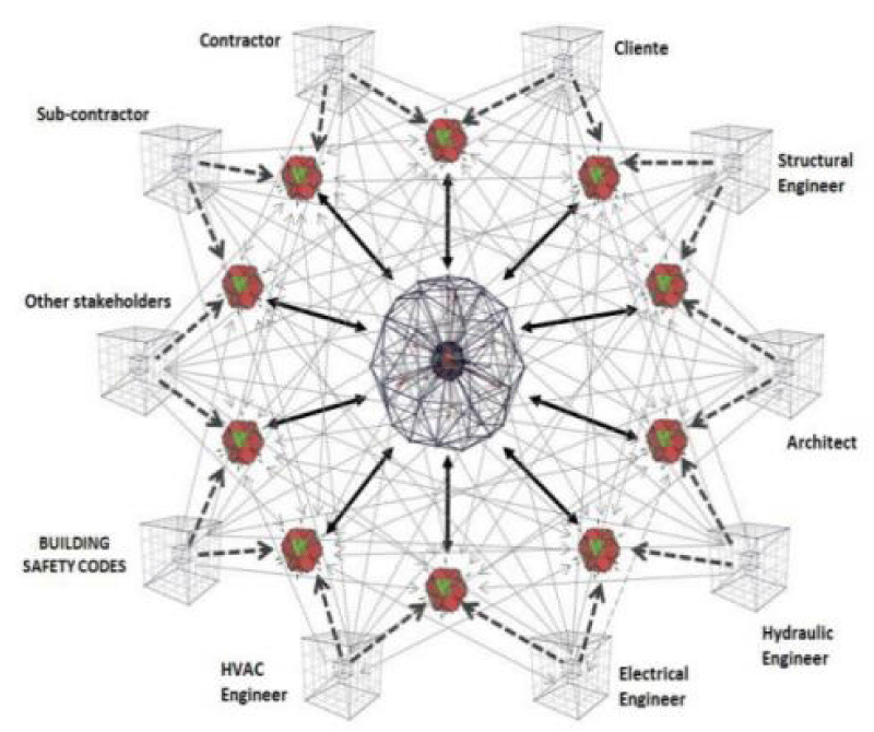
BIM has been implemented in the sector, with recognized benefits registered worldwide. It has contributed to the agility of project development, replacing the traditional way of using Computer Aided Design (CAD) tools, which are based on digital drawings that require manual work and are susceptible to misinterpretations and inconsistencies. The BIM concept is based on the generation of a federated three-dimensional (3D) model, containing the information relative to all the project disciplines in a centralized and accessible way, and easily shared among all entities (Figure 1). The adoption of BIM promotes collaboration and accurate detection of inconsistency at the design stage, which naturally leads to less effort and lowers costs associated with the possible need for subsequent correction.
Although this methodology is promising, there is still some resistance to its development, not only due to the high investment that offices have to make in equipment, software, and training but also due to the limitations that still exist in the use of the available BIM-based systems, which present themselves to the engineer as an unsolved problem.
As this is the inevitable step to take in project design companies, this paper aims to contribute to the investigation of this methodology, promoting its dissemination in the sector. Thus, the main objective of the work is to analyze, through a practical case, the implementation of the BIM methodology in structural design: evaluating the efficiency of the use of BIM tools in the different phases of structural design (design, analysis and structural dimensioning); exploring the various applications that the BIM model presents related to the different dimensions that the methodology presents.
BIM methodology
Parametric modeling
Parametric modeling is the process of generating an object-oriented 3D model associated with parameters that can be manipulated by the designer, in terms of their geometry, applied material, and other information [2].
The BIM model is represented by a set of parametric objects that contain a variety of data, which can be used as input for further tasks, such as extracting quantities of materials to support budgeting or carrying out structural, energy, or sustainability analyses.
Dimensions of BIM
BIM methodology has a wide range of applications that satisfy different objectives based on the project information contained in the BIM model. These tasks correspond to the different BIM dimensions and are called nD BIM [3]:
- 3D BIM represents the set of 3D parametric objects referring to all the specialties (geometry, spatial inter- relation, physical properties of the materials, the identity of each element,…);
- 4D BIM is concerned with the planning of the construction process associating the model to the critical path chain studied;
- 5D BIM is related to project costs supported by the quantity take-off;
- 6D BIM supports the performance of sustainability studies, namely the estimation of energy consumption and its monitoring during building occupation;
- 7D BIM is considered in the management and maintenance of the building during its period of use;
- 8D BIM is related to safety risks during construction supporting the establishment of preventive action plans.
Implementation strategy
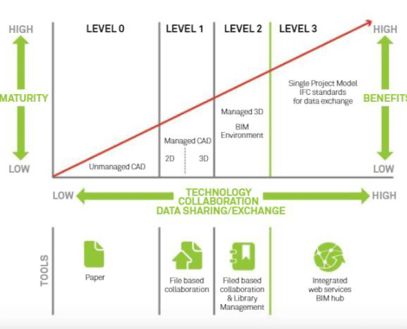
In order to establish the collaborative capacities in a company, maturity stages were defined through the Bew-Richards matrix, (Figure 2). Currently obtaining level 2 is a considerable achievement, since the available BIM resources have limitations that delay the implementation of level 3. This paper demonstrates that it is possible to reach the stage of full collaboration (level 2).
Every project requires a well-defined strategy for the implementation of BIM, where all entities know exactly how to collaborate in every phase of the project. The BIM execution plan (PEB) is the formal document written before the beginning of the project that has that information.
BIM in structural design
Within the scope of this study, interviews were carried out with structural design offices that have been implementing BIM in project development, and research was carried out on the advantages and limitations of BIM in structures, allowing the identification of some difficulties and benefits in the application of BIM:
- The transition to BIM does not result in an immediate improvement in productivity as expected. Initially, there will always be a decrease. However, the higher the investment, the steeper the learning curve
- The use of BIM tools contributes to the optimization of structural modeling (conception), coordination (inter-discipline), and documentation (production of drawings) [5].
- Increased quality is achieved due to clash detection tools, consistent drawings, and great accuracy in quantity take-off.
- Insufficient knowledge of BIM by some professionals limits the collaboration potential of the methodology
- Lack of confidence in the quality of the analytical model generated and of the transferred data due to the ineffective level of interoperability between the modeling and calculation software.
Case study – structural model
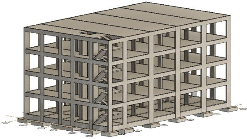
In this paper, a reinforced concrete structure of a project was developed concerning a four-story residential building (category A [6]) located in Lisbon. The generated model was based on a set of drawings of floor plans, section cuts, and details of the structure. The structure is composed of orthogonal frames which support the floor slabs. Each floor is formed by a set of parallel beams that are oriented according to the smallest direction.
The isolated footings are 0.60m thick and are connected to each other by foundation lintels placed in both directions Figure 3.
Physical model
The modeling software used was Revit from Autodesk. There were significant changes verified during the conception of the structure when compared to the traditional method:
- Revit enables the introduction of the coordinates in the survey point and project base point allowing all objects to have their real coordinates and elevation associated.
- Since this involves 3D modeling, when the solution is created in a plan view, it will be reflected in all other plans. An additional advantage is that the structure can be observed in 3D, contributing to a clearer comprehension of the conception.
- The project browser should be organized in order to improve collaboration and avoid damaging others’ work.
- Schedules (dynamic tables) are a way to examine the project and also to manipulate it. It simplifies the detection of inconsistencies regarding the type of information each object is associated with.
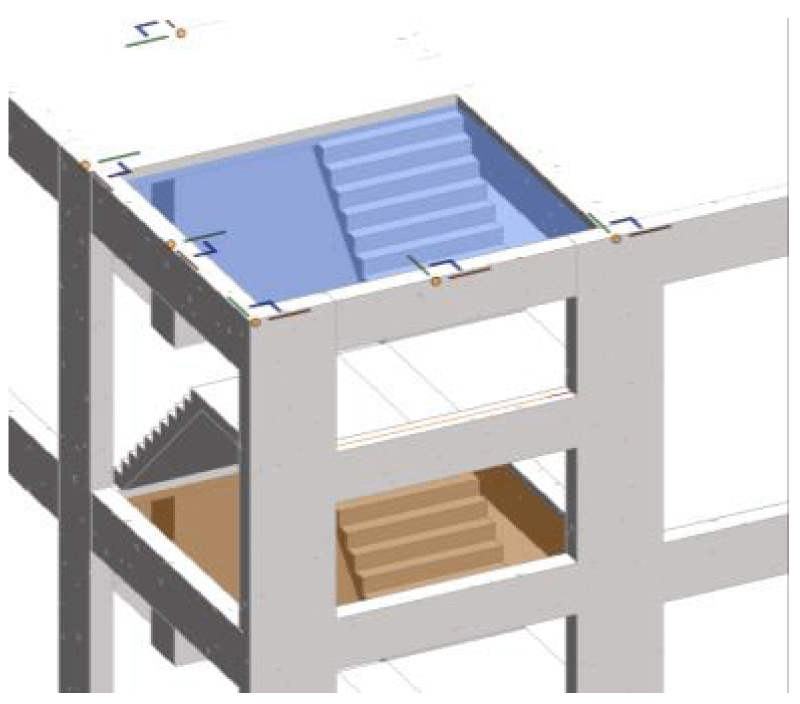
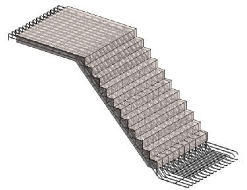
Revit has a structural menu with a variety of objects to model the solution. Each object must be modeled according to the tool of the corresponding category to avoid subsequent errors. This was only not applied in the case of the stairs, because Revit only considers this as an architectural object. Thus, it was modeled as an element of the category slab, with the geometry of the stair, so it would be possible to insert reinforcement.
Analytical model
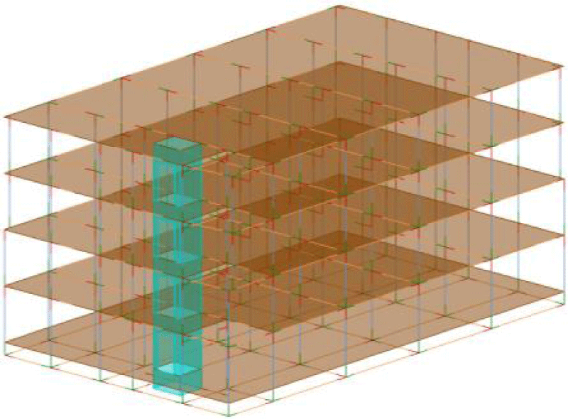
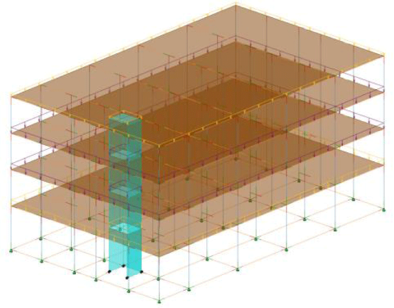
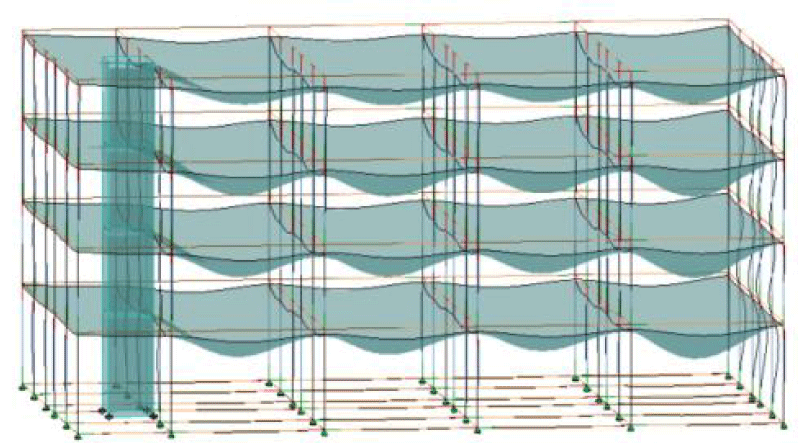
After modeling the structural elements, Revit enables the automatic generation of an analytical model (Figure 4), since the physical structural objects have attributes associated with the finite element method (FEM) and physical properties. Despite the analytical model being generated automatically, the engineer needs to carefully check its consistency.
Analytical model adjustments
Through the observation of the generated analytical model, inconsistencies were identified. Therefore, several types of adjustments were made before transposing it to the calculation program:
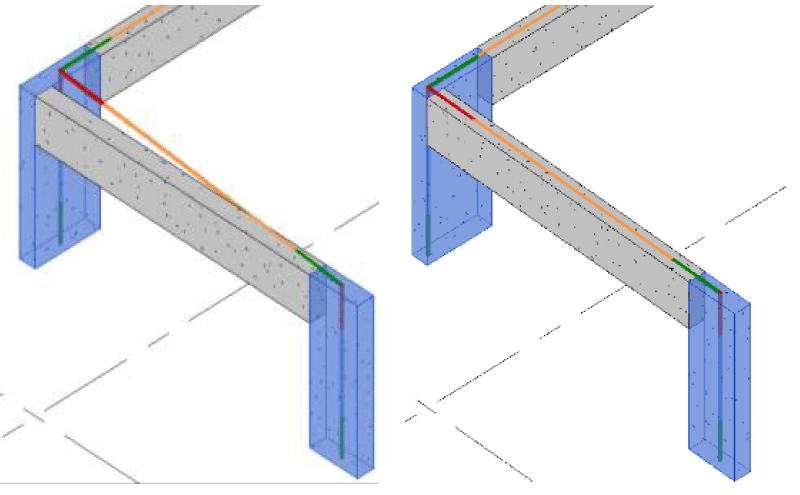
- It is frequently verified that certain FEM elements are not placed on the orthogonal axis, which can cause unwanted effects in the calculation. The analytical beams were inclined towards the orthogonal axis since the analytical representation of the column was located at its geometric center, which does not coincide with the intersection of the axis of the beams. Thus, the column was positioned on the desired reference line by modifying the Base and Top Alignment in the Analytical alignment property of the analytical column.
- The ground floor was modeled as a slab element. However, this element does not have the function of resisting the stresses to which the structure is subjected, and is not intended to appear in the calculation model. Thus, in the element properties, the characteristic “Structural” is removed (Figure 5).
Whenever it is not possible to adjust the analytical element through its properties, Revit allows manual adjustment, where a node of the analytical model is dragged independently of the physical one (Figure 6).
In Revit, the analytical representation of the footings corresponds to nodes, which after exporting to Robot are converted into a clamped support. However, if boundary conditions are applied in Revit, Robot assumes that information. In this case, a pinned support was applied at the base of the columns.
Once the adjustments have been completed, Revit has tools that automatically check its consistency Figure 7.
Structural analysis and design
Revit is able to communicate directly with Robot structural analysis professionals, allowing them to send/update the whole model or pre-selected parts.
After a consistency check of the model, it was verified that all data was transferred correctly, except the value of the spring stiffness of the elastic support which was incorrect. The insertion of the actions and their combinations should be made in Robot in order to avoid possible errors in the transfer and to increase efficiency since it can automatically generate the combinations effectively.
Reinforcement design
The robot allows an automatic determination of the reinforcement according to the Portuguese regulations of Eurocodes 2 and 8 [7,8]. There are two main steps in this process:
- Calculation of the required reinforcement (At), which refers to the theoretical reinforcement area required;
- Definition of provided reinforcement (Ar) which determines the area of the reinforcement that is actually placed, which must be greater than at.
In the determination of the provided reinforcement, several parameters are manipulated in order to design a solution according to the idea of the user. When the reinforcement is calculated, the Robot displays the solution in plans, 3D views, and drawings (Figure 8). A report is also generated with the calculations performed to verify the safety of the element.
The programs should not take responsibility away from the engineer, but optimize time, in finding a better solution instead of repetitive tasks.
Software interoperability
After the design has been prepared, it is possible to update the Revit model so that it has made the reinforcement detail:
- For slabs, it is possible to build an effective reinforcement solution. However, it only allows sending the diagrams of forces and required reinforcement to Revit. The core walls do not support the calculations of the reinforcement according to Portuguese standards.
- In the case of the beams, the most efficient calculation process and the one that leads to better interoperability is when this is modeled as a single multi-span beam.
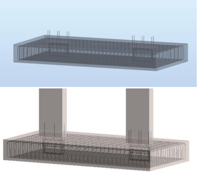
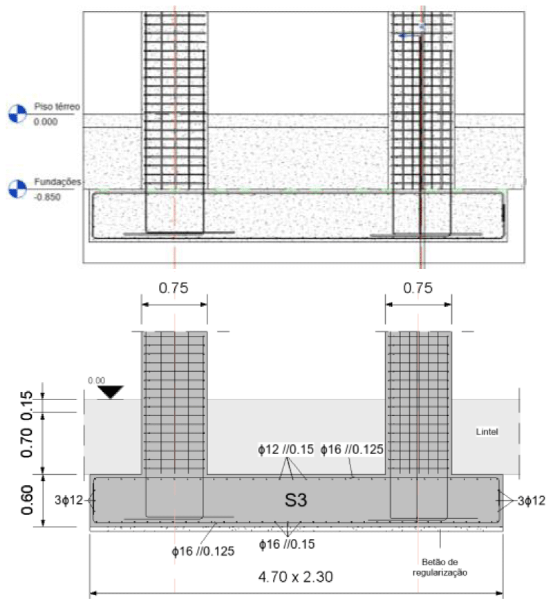
Regarding columns and foundations (Figure 9) either the interoperability or the automatic calculation are both fine despite some required manual adjustments.
Reinforcement modeling in Revit
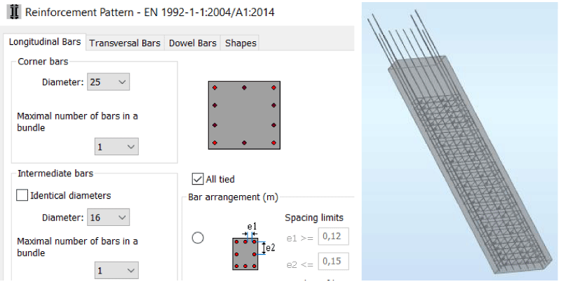
Rebar modeling in Revit is intuitive and versatile, allowing advantages such as obtaining reinforcement details with automatic identification and accurate immediate quantity take-off. However, it can be an exhaustive task to model the whole reinforcement of the structure Figure 10.
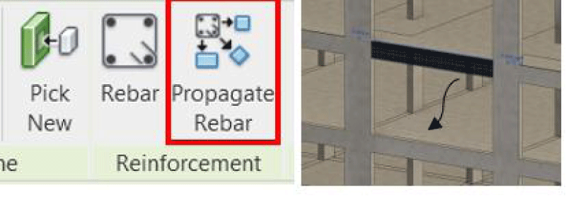
The most recent version Revit 2023 has an option called Propagate Rebar which allows the user to copy a detailed reinforcement from one object to another similar one, avoiding repetition in modeling, and increasing efficiency Figure 11.
Management of the BIM model
A BIM model consists of parametric objects that contain multiple pieces of information besides the geometric one. This enables several applications related to the various BIM dimensions initially mentioned below:
Coordination and collaboration
Revit saves the information about the results of the diagrams of forces, displacements, and the required reinforcement area of each element from the calculation performed in Robot. The ability to centralize information is quite helpful when, in a reinforcement modeling or design review process, you want to consult data from the structural analysis Figure 12.
One of the most used applications is the capacity to detect conflicts between specialties in an automatic way. This adaptation is extremely relevant since it is not possible to spot inconsistencies in the project so quickly, that would be otherwise only identified and resolved on-site.
Drawing preparation
The drawings are sets of views and details of the structure containing all the graphic information that facilitates the execution of the structure on site. The great advantage of BIM programs compared to CAD tools is that all sections, plans, and details can be generated automatically and there are no inconsistencies between drawings. However, the development of a drawing, from the application of a section to the required technical drawing, needs some work and mastery of the systems’ support functionalities. Formatting drawings is a task that causes a decrease in productivity, as it still requires repetitive work Figure 13.
4D and 8D dimensions
Associating a time variable to each object of the model, it is possible to simulate the phasing of the construction, thus facilitating its planning. The simulated representation of the construction assists the risk assessment that the worker may experience, identifying the phases and areas of the construction site that require special attention in terms of precautions.
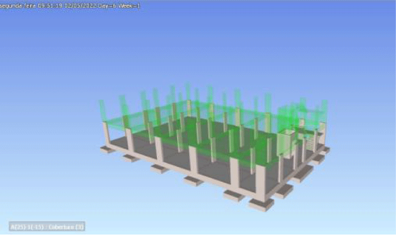
After exploring the timeline tool of the software Navisworks Manage, it is concluded that correct object modeling and classification are essential for the proper tracking of information, allowing an efficient generation of a visual simulation of task planning on-site Figure 14.
5D dimension
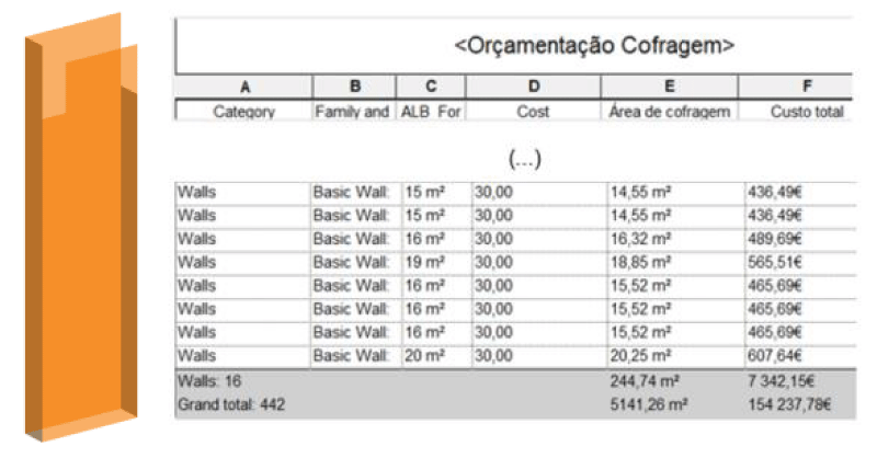
The task of estimating the costs of a structural project can be carried out on the BIM model by associating a unit cost to each material or object. The extraction of quantity from the model is an automatic task, through the creation of dynamic tables (schedules) since every object has information about its volume. At any stage of the project, the engineer can consult the schedules created to monitor the economic impact of the structure being created. This functionality is crucial in the technical-economic study of different solutions.
To include formwork in this paper, a plug-in from alphabim was used, which generates the formwork needed for each element based on a set of rules defined by the user Figure 15.
The data generated in schedules can be manipulated and exported to Excel in order to create the quantity take-off sheets of the amount of each material used in the structural solution.
6D dimension
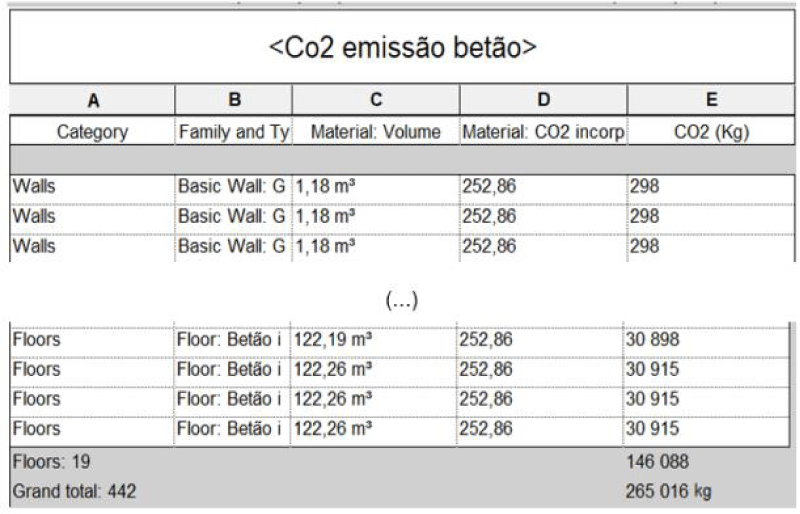
A sixth dimension can be included in the model, by attributing the information on the amount of CO2 incorporated in each element. Through the visualization of schedules, it is possible to estimate the number of carbon emissions of each material used in the structure, supporting the decision-making of the solution Figure 16.
Conclusion
This paper demonstrates the several benefits and limitations that should be considered when adopting the BIM methodology. It also shows the advantages and applications provided by a model that has a high quantity of centralized information.
- BIM tools, due to their 3D geometric feature, enable the conception of a better solution, not only because it is easier to observe the structure that is being developed, but also due to the facility in observing the constraints of the solutions modeled by other disciplines.
- The BIM model, due to the fact that it contains parametric objects with several attributes, allows the manipulation and organization of information in order to compose drawings and extract quantities. In addition, whenever there is a change in the project, all the information is updated, with no need to modify it manually.
- The analytical model can be associated with the BIM model, allowing an integrated structural analysis and design. In this way, the centralized model is coherent with the calculations made.
- Nevertheless, there are certain bottlenecks that delay the further implementation of BIM:
- The investment is considerable and there is always a decrease in productivity during the adaptation phase.
- The analytical model is not yet completely independent from the physical one, which prevents the engineer from making the simplifications required.
- The automatic design does not yet allow a solution to be developed with the intended accuracy.
- Interoperability is still limited and may not provide engineers with the confidence necessary.
Despite some limitations, there is, however, some optimism in the adoption of BIM in structural design, either due to competition needs in a global world, or because the new generation of engineers is culturally more technological. Technological innovation is growing exponentially and it is necessary that the industry is aware and open-minded in the search for solutions in order to achieve more efficient and better-quality construction.
General, seismic actions and building rules, 2009.
- Musayelyan H. Architectural design decision support system. 2009.
- Teicholz P, Eastman CM, Sacks R, Liston K. BIM Handbook A guide to Building Infomation modeling, 2011.
- Sampaio Z. Maturity of BIM Implementation in Construction Industry. 2021.
- Langdon D. Getting the most out of bim: guides for clients. Aecom. 2011.
- Shinler D, Nelson PE. BIM and the structural Engineering Community. https://www.structuremag.org/wp- content/uploads/2014/08/C-Tech-BIM- SchinlerNelson-Dec-08.pdf.
- CEN. Portuguese Standard EN1990 - Eurocode 0 - Basis for the design of structures. 2009; 47.
- CEN. Portuguese Standard EN 1992-1-1-Eurocode 2–Design of concrete structures - Part 1-1: General rules and regulations for buildings. 2010.
- CEN. Portuguese Standard EN 1998-1-1-Eurocode 8 - Design of structures for earthquake resistance; Part 1: Rules.
Article Alerts
Subscribe to our articles alerts and stay tuned.
 This work is licensed under a Creative Commons Attribution 4.0 International License.


 Save to Mendeley
