Journal of Civil Engineering and Environmental Sciences
Eco-Friendly Industrial Biofuel Oven From Locally Sourced Renewable Agricultural Waste
1Faculty of Engineering, Nnamdi Azikiwe University, Awka, Nigeria
2Faculty of Engineering, Alex Ekwueme Federal University, Ndufu-Alike Ikwo, Nigeria
3National Board of Technical Education (NBTE) South-East Zonal Office, Awka, Nigeria
Author and article information
Cite this as
Nwambu C, et al. Eco-Friendly Industrial Biofuel Oven From Locally Sourced Renewable Agricultural Waste. J Civil Eng Environ Sci. 2026; 12(1): 7-13. Available from: 10.17352/jcees.000099
Copyright License
© 2026 Nwambu C, et al. This is an open-access article distributed under the terms of the Creative Commons Attribution License, which permits unrestricted use, distribution, and reproduction in any medium, provided the original author and source are credited.The study design and develop a highly energy-efficient biomass stove using waste biomass as fuel and recovering waste heat from the combustion chamber for the drying function. The system uses a single thermal energy source to power both the drying and product chambers. Four industrial thermometers were placed in each of the three chambers and one outside to simultaneously record their instantaneous temperature values. Temperature data were taken every 20 seconds for the duration of the 900-second experiment. Only the three thermometers in the chambers started to react appropriately as soon as the combustion began. The combustion chamber recorded 520⁰C, the product chamber recorded 98⁰C, and the drying chamber recorded 170⁰C after 900 seconds. Calculations reveal that during the same period, the combustion chamber produced 891.00J/s of heat energy, while the drying and product chambers absorbed 217.50J/s and 569.70J/s, respectively. Consequently, the product and drying chambers’ thermal efficiencies are reported as 63.94% and 24.41%, respectively, bringing the system’s overall thermal efficiency to 88.35% with the system ultimately losing 11.63% of the total thermal energy generated. The composite insulation enhanced the thermal insulation of the system, thereby contributing to its improved conservation of energy. Therefore, to achieve optimal thermal energy consumption and improved thermal efficiency in the heating of food items, this biomass stove will be crucial. Waste biomass is a good source of thermal energy that can be used in place of other energy sources, particularly fossil fuels, and end the devastating effects of the energy challenge in the agro-processing industry.
Every country in the world works to meet the energy needs of homes and businesses, with agro-processing being a major concern. A huge quantity of thermal energy is being consumed on a daily basis in the agro-processing business [1-7]. The relevance of thermal energy in the agro-processing industry can never be over-emphasized. The agro-processing industry requires energy for heating, cooling, drying, and electricity, and the total energy demand for food processing is about three times the direct energy consumed behind the farm gate [1, 6-14]. Rice, palm oil, garri, and fish agro-processing plants consume large amounts of thermal energy during parboiling, sterilization, frying, and drying, respectively. For fish processing, the direct energy demand for canning, freezing, drying, and producing fish meal and fish oil by-products is very high. Drying is a highly energy-intensive process, accounting for 10–20% of total industrial energy use in most developed countries [15-29]. The demand for energy for rice processing increases every year, and energy conservation in rice processing industries would be a viable option to reduce the intensity of energy by increasing the efficiency of rice processing systems, which leads to a reduction in emissions and an increased supply of rice husk energy to other sectors as well [3]. Agriculture is heavily reliant on energy as a production factor, which makes it highly susceptible to energy prices and energy availability [5, 27-31]. More so, Power unreliability and unavailability have prompted industrial firms, households, and commercial enterprises to depend on private diesel and petrol-fueled generators [6-8. Increasing dependence on energy usage (mainly fossil fuels) throughout the entire food chain raises concerns about the impact of high or variable energy prices on production costs, competitiveness, the final price of food for the consumer, as well as concerns about energy security [3,9]. As a result, the global energy crisis has called for a diversion from the sustained utilization of fossil fuels [10-18].
Therefore, the idea of this proposal is to design and produce a biomass dual thermal system for food processing plants by utilizing some locally sourced eco-friendly materials like sawdust. This project will produce a healthy, well-improved, low-cost, bio-based, and commercialized biomass stove, to expand the income-earning opportunities for Nigerians and other countries, and to create job opportunities for industrial-driven people who may want to be trained on biomass stove production from agro-processing waste.
Experimental Procedure
The experimental materials are as follow; stainless steel plate, mild steel plates, angular bar (mild steel) industrial thermometer, biomass feedstock (sawdust), plaster of paris (POP), plywood board, cassava starch, water, cooking gas cylinder, 4-inch hollow pipe, 1-inch hollow pipe, 32-ton hydraulic jack, press and stirrer: The four (4) thermometers with different temperature ranges (0⁰C - 650⁰C, 25⁰C - 650⁰C, 0⁰C - 120⁰C and 0⁰C - 60⁰C) were used in the study (Figure 1).
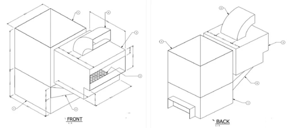
(1) Combustion chamber, (2) Product chamber, (3) Drying chamber, (4) Chimney, (5) Perforated drying tray, (6) Exhaust pipe, (7) Plaster of Paris (POP), (8) Plywood board.
The biomass dual thermal system is made up of three main chambers, namely, the combustion chamber, the product chamber, and the drying chamber. Additionally, it also has several relevant components, which are: a flat plate heat exchanger, chimney, exhaust pipe, and composite insulated wall. The biomass stove was developed by means of welding and carpentry work. The metallic sheets were measured and cut to the required dimensions. The product and combustion chambers were the first to be built, and then the making of the drying chamber was made. Next was the making of the chimney component, which was used as a connector to weld the drying chamber to the combustion chamber. The welded work was then welded to a flat rectangular base, which gave it firm support while the remaining work continued. The angular bar metal was welded around the base to serve as its stand and to hold the composite insulators in their appropriate positions. The exhaust pipe was designed and welded to the top of the drying chamber. The woods were measured based on the external dimensions of the system using a measuring tape. Screw nails were used to hold them together on the external curved surface of the thermal system to insulate it against heat loss. In the body framework, the wood is prevented from making direct contact with the metallic surfaces by creating a 30 mm gap around the system externally. This gap is filled with Plaster of Paris, which gives rise to composite insulation in order to boost the thermal insulation.
Preparation of biomass briquette involves pouring one (1) litre of water into a 5-litre metallic cylindrical container, 0.2litres of solid starch was disintegrated into it and was thoroughly stirred. The container was placed over a fire and continuously stirred until a gelatinous solution was obtained. A 5-litre volume of sawdust was gradually poured into the starch solution and continuously stirred with a paddle to obtain a uniform mixture. Afterwards, the mixture was fed into a small pipe (of 4 inches diameter) with a smaller hollow pipe (of 1 inch diameter) placed in the middle. With the help of a hydraulic jack, the biomass was subjected to a compressive force to an extent and allowed to stay for 20 minutes before being disengaged.
The experiment was conducted between 9.30 am and 10.00 am. 0.8kg of biomass briquettes was fed into the combustion chamber and well placed on the perforated plate. The four (4) industrial thermometers were carefully and well positioned in the combustion chamber, product chamber, drying chamber, and the surrounding areas, respectively. The biomass briquettes were ignited and allowed to burn for the next 900 seconds (15 minutes). The temperature readings were taken concurrently at intervals of 20 seconds throughout the experimental duration. All the temperature readings were then tabulated for further analysis (Figure 2).
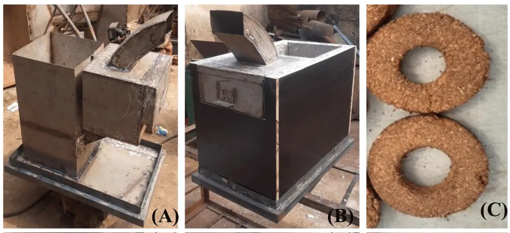
Rate of heat supplied from the combustion chamber
During the combustion process in the combustion chamber, heat was generated from the biomass briquette and conveyed away from its surface by the convective heat transfer process. Hence, the rate of heat energy supplied is given by (Rajput, 2008):
Qcc = hA (Tcc - T∞) (1)
Where Qcc is the rate of heat energy supplied from the combustion chamber
h is the convective heat transfer coefficient
A is the cross-sectional area of the product chamber base
Tcc is the surface temperature within the combustion chamber
T∞ is the ambient temperature
Rate of heat transferred to product chamber
Heat transferred to the product chamber is given by (Rajput, 2008):
Qpc = -k A (2)
where Qpc is the heat transferred to the product chamber
A is the base surface area of the product chamber
k is the thermal conductivity of the base (stainless steel flat plate)
is the temperature gradient
T1 is surface temperature at x1 (T1 – Tcc)
T2 is surface temperature at x1 (T2 – Tpc)
x1 – x2 = Thickness of stainless-steel flat plate
Rate of heat transferred to the drying chamber
Heat transferred to the drying chamber is given by (Rajput, 2008):
Qcc = hA (Tdc - T∞) (4)
Where Qdc is the rate of heat energy supplied from the combustion chamber
h is the convective heat transfer coefficient
A is the cross-sectional area of the product chamber base
Tdc is the temperature within the drying chamber
T∞ is the surrounding temperature
Thermal efficiency for the product chamber
Thermal Efficiency for the product chamber is given by:
Thermal efficiency for the drying chamber
The thermal efficiency for the drying chamber is given by:
Overall thermal efficiency for the entire system
The overall thermal efficiency for the system is given by:
Overall heat transfer coefficient for the system (Figure 3)
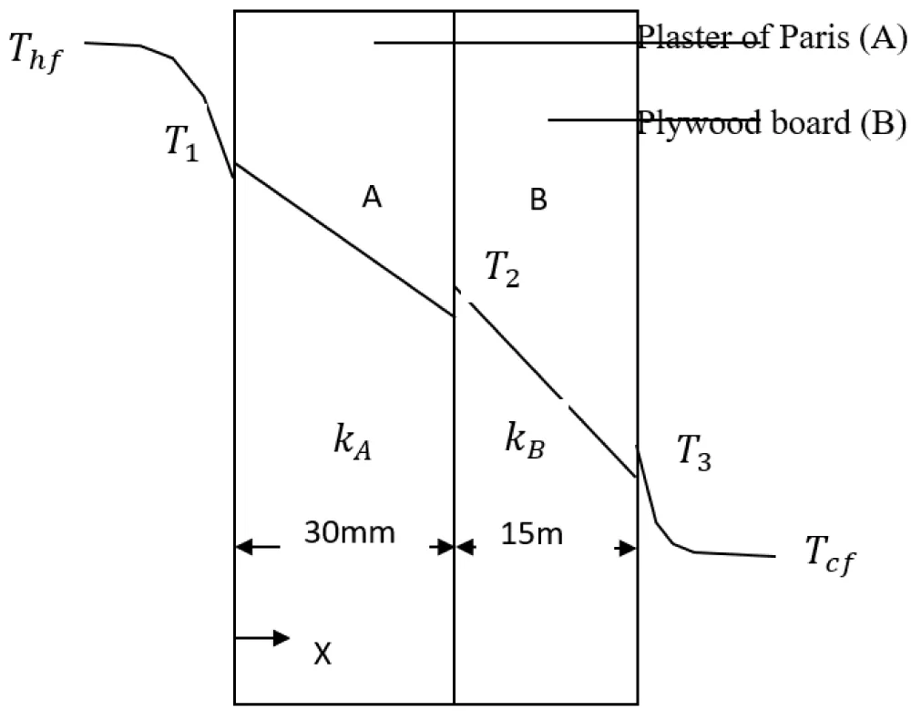
The heat transfer rate through a composite wall, Q = UAΔT, where U is the overall heat transfer coefficient, and A is the surface Thf area of the composite wall. And ΔT is the overall temperature difference.
Therefore, U =
Where Thf is temperature of the hot fluid, T1 is temperature of surface 1, T2 is temperature of surface 2 (interface) between POP and plywood board, T3 is temperature of surface 3, Tcf is temperature of cold fluid, kA is thermal conductivity of A-slab (POP), kB is thermal conductivity of B-slab (Plywood board), LA is thickness of slab A, LB is thickness of slab B, h1 is convective heat transfer coefficient of fluid 1, h2 is convective heat transfer coefficient of fluid 2.
Result and discussions
Figure 3.1 shows the variation of temperatures of the three chambers with time. Hence, as combustion began to take place, it was observed that the temperature readings on the three thermometers placed in the chambers showed no observable change in temperature in the first 60 seconds of the experiment. After 120 seconds, there was a bit of a sharp increase in temperature in the combustion chamber, followed by the temperature values in the other two chambers some seconds later. While the experiment progressed further, the various temperatures increased accordingly. The temperature readings in the combustion chamber were the fastest, the temperature readings in the drying chamber were next, and the temperature readings in the product chamber were the slowest. For instance, where the temperature readings, say, at point 15 (280 seconds), the combustion, product, and drying chambers recorded 155⁰C, 48⁰C and 75⁰C respectively. The same trend continued till the last point (900seconds) where the final temperature readings from the chambers were recorded as 520⁰C, 98⁰C and 170⁰C respectively. As the product and drying chambers absorb heat energy, Tpc and Tdc increase at different rates.
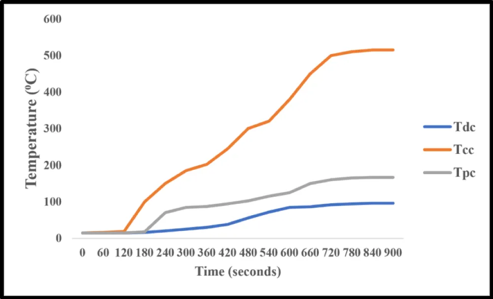
Figure 4.0 shows the various values of thermal energy obtained concurrently in the three chambers during the experiment. As the experiment progressed, the values of the thermal energy were observed to increase accordingly. Figure 4.0 reveals unique information instead. As thermal energy continued to be generated and supplied from the combustion chamber, the rate at which thermal energy was being absorbed was much higher for the product chamber than for the drying chamber. At the same point 15 (280 seconds), the combustion, product, and drying chambers recorded 234.00J/s, 144.45J/s, and 75.00J/s respectively. The same trend continued to the final point of the experiment, where the combustion chamber supplied 891.00J/s, the product chamber and drying chamber absorbed 569.7J/s and 217.5J/s of thermal energy, respectively. Basically, product and drying chambers received heat by conduction and convection, respectively, which have different heat transfer controlling laws (Figure 4).
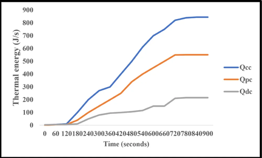
Figure 5 shows the amount of generated thermal energy from the combustion chamber and the corresponding amounts distributed to the product and drying chambers, in addition to the residual energy lost to the surroundings. Hence, 569.7J/s and 217.5J/s of thermal energy were absorbed by the product and drying chambers, respectively, as 103.8J/s of the generated thermal energy got lost to the surroundings.
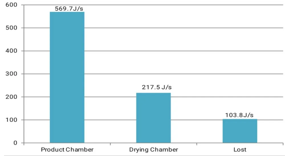
Figure 6 shows the thermal efficiencies of the product and drying chambers. Hence, the product chamber absorbed 63.94% of the total thermal energy generated from the combustion chamber, while the drying chamber absorbed 24.41% of the total thermal energy generated.
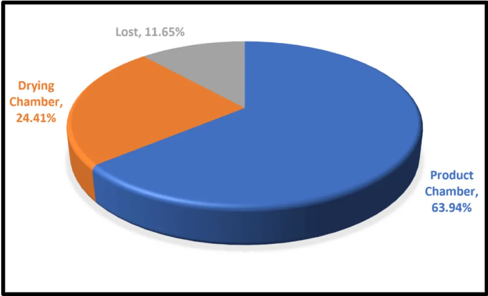
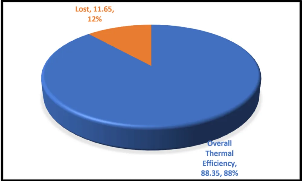
Figure 7 shows the overall thermal efficiency of the biomass dual thermal system, which is 88.35%, and the corresponding 11.65% of the generated thermal energy lost to the surroundings. The recovery of most of the lost thermal energy from the combustion chamber boosted the 63.94% thermal efficiency of the product chamber to the 88.35% overall thermal efficiency of the system.
The final temperatures obtained at the end of the experiment are: 520⁰C for the combustion chamber, 98⁰C for the product chamber, and 170⁰C for the drying chambers. The combustion chamber generated 891.00J/s of thermal energy. 569.70J/s of the generated thermal energy from the combustion chamber was transferred to the product chamber, which gave rise to 63.94% thermal efficiency of the product chamber. 217.50J/s of the generated thermal energy was transferred to the drying chamber, resulting in 24.41% thermal efficiency of the drying chamber. The total rate of heat energy transferred to both the product chamber and drying chamber is 787.20J/s. The overall thermal efficiency for the entire thermal system is 88.35%. 11.65% (103.80J/s) of the generated thermal energy from the combustion chamber was totally lost by the system to the surroundings. 321.30J/s of thermal energy is not transferred to the product chamber for the primary thermal function. 67.69% of the waste heat lost from the combustion chamber was recovered and transferred to the drying chamber. 32.31% (103.80J/s) of the waste thermal energy finally got lost to the surroundings. The external surface of the composite insulators remained at the surrounding temperature. Throughout the duration of the experimental work, the combustion process remained active without any external aid of supplying air by forced convection. During the combustion process, there was no backflow of smoke through the air-inlet opening of the combustion chamber; rather, all smoke left through the exit end (chimney) of the combustion chamber [28-32].
Further analysis
The findings will go a long way towards helping food processing plants to achieve a drastic reduction in the amount of energy consumption. Applying the biomass stove thermal model in the agro-processing plants will result in increased thermal efficiency, of which most of the heat energy being lost will be recovered for carrying out other thermal functions, like drying of freshly prepared biomass briquettes and even the drying of food items. In this regard, too, the composite insulation is of great relevance as it enhances the conservation of thermal energy by the thermal system.
Secondly, from the findings, the use of waste biomass as a generously affordable source of thermal energy will bring about a tremendous reduction in the cost of energy consumption. When this is implemented, the cost of energy consumption will drop, thereby affecting the overall agro-processing plant’s cost of production positively and then boosting the gross profit margin. The design model promotes self-reliance in the generation of thermal energy. As a result, the built-in drying chamber in the thermal system efficiently handles the drying stage in the biomass briquette production and makes them available whenever needed. This feature addresses the greatest challenge in processing biomass, which lies in its drying. With sawdust as the biomass feedstock, no further grinding is required. Hence, sawdust feedstock takes much less time to process into biomass briquettes than most other biomass feedstock that usually requires grinding. With the application of the biomass dual thermal system design model, one critical implication of it is getting our environment free of such waste and keeping the environment safe. The non-use of the waste biomass at the time being has caused widespread dumping in every available space, leading to environmental degradation. Thus, with a gradual increase in the utilization of the waste biomass, their economic value will improve, and they will be neatly managed, which will lead to a much safer environment. Another implication of the findings is that the thermal model is very convenient during application. The various components and sections of the thermal system are appropriately figured out and engineered so that its simplicity makes it highly user-friendly. The findings from this study entail great prospects for the agro-processing industry, where the utilization of thermal energy is applicable. It is highly recommended for the garri, rice, palm oil, fish processing businesses, etc., as an appropriate thermal model to contribute immensely towards optimal energy and improved thermal efficiency in the industry. The waste biomass obtained from these food processing plants, coupled with the enormous amount of thermal energy generated on a daily basis, is sufficient enough to be harnessed for providing the thermal energy needed for their heating activities.
Conclusion
This research work on Evaluation of Thermal Performance of a Locally Produced Biomass Stove has shown that waste heat energy from agro- processing plants can be efficiently recovered and harnessed for thermal functions like food heating, drying of food items, and even the drying of freshly prepared biomass briquettes. The temperature of 170⁰C and thermal efficiency of approximately 24% obtained for the drying chamber is a clear indication that a great deal of agro-processing thermal activities can be achieved by harnessing the recovered waste heat from the combustion chamber. The design of the biomass stove equally contributed to the improved thermal efficiency of the entire system. The perforated square plate placed inside the combustion chamber, which is held fixed 10mm uniformly above the base, carries the bulk of the burning biomass briquette. The plate enhances the steady supply of air from beneath the plate, which carries the biomass briquette and creates steady oxidation of the combustion process. More so, the design of the chimney, with a cross-sectional dimension of 150mm long by 80mm wide, allows a small amount of air movement through it to the drying chamber. Also, the biomass packing rack in the drying chamber is perforated completely and raised 10mm above the base. This plate creates a uniform distribution of thermal energy in the drying chamber and leaves the chamber through the exhaust. Based on the fact that the sawdust biomass briquette burned moderately during the experiment, this research has shown that waste biomass is also a good source of energy for generating thermal energy for agro-processing thermal functions. Even as sawdust is available in very large amounts at sawmills, agricultural crop residues like cassava peels, rice husks, coconut shells, etc., are also largely available at agro-processing plants. These items are being discarded with reckless abandon in our environments. As a matter of fact, the waste biomass costs basically nothing and with very low processing cost into useful energy resource. Hence, the research work has shown that waste biomass is the next alternative source of thermal energy for achieving most of the thermal activities at agro-processing plants. This will tremendously help agro-processing plants to cut down on their huge expenditures on power, thereby getting a low cost of production and gaining much more in net profit.
Acknowledgement
The authors acknowledge funding from the Tertiary Education Trust Fund (TETFUND) with reference number TETF/ES/DR&D/CE/UNI/AWKA/IBR/2026/VOL.1. The authors also thank the following: Metallurgical and Materials Engineering Department Workshop of Nnamdi Azikiwe University, Awka, Anambra State, where we did our fabrication and testing job; we remain indebted to all.
- Achebe CH, Umeji AC, Chukwuneke JL. Energy evaluation of various compositions of biomass waste briquettes. Adv Res. 2024;13(6):1-11. Available from: https://doi.org/10.9734/AIR/2018/39270
- Adapa PK. Performance study of a heat pump assisted dryer system for specialty crops [MEng thesis]. Saskatoon (SK): University of Saskatchewan, Department of Mechanical Engineering; 2021. Available from: file:///C:/Users/admin/Downloads/Adapa_Phani_Kumar_2001_sec.pdf
- Anyafulu UU, Ekwedigwe CM, Nwambu CN, Nnuka EE. Effect of bismuth and lead on the mechanical properties of aluminium-4% copper alloy. UNIZIK J Eng Appl Sci. 2024;3(2):691-698.
- Ayodele. Effect of sand dust and eggshell ash on selected engineering properties of laterized brick. Niger J Soil Sci. 2019. Available from: https://doi.org/10.4314/njt.v38i2.1
- Ezeobi UE, Nwambu CN, Nnuka EE. Influence of heat treatment parameters on mechanical properties and microstructure of Cu-10wt%Si-2wt%Ni alloy. UNIZIK J Eng Appl Sci. 2024;3(2):666-674.
- Ekwedigwe C, Nnakwo K, Nwambu C. Viscoelastic properties of alkaline treated walnut shell/rice straw fiber/epoxy biocomposite. J Civ Eng Environ Sci. 2023;9(1):9-13. Available from: https://doi.org/10.17352/2455-488X.000061
- Ilona EI, Nwambu CN, Nnuka EE. Effect of modification on the structure and mechanical properties of aluminium-12% silicon alloy. Int J Sci Eng Res. 2016;7:471-475.
- Imamudeen B, Nwambu CN, Nwoye CI. Effect of soil physical properties on the corrosion of underground API 5LX70 steel pipeline along Kaduna-Kano, Nigeria. UNIZIK J Eng Appl Sci. 2024;3(2):756-763.
- Iyebeye KO, Nwambu CN, Nnuka EE. Investigating the effects of lanthanum and tin additions on the structure and physico-mechanical properties of Cu-30%Zn alloy. UNIZIK J Eng Appl Sci. 2024;3(2):735 -755. Available from: https://www.civilengineeringjournals.com/ijsse/article/31/5-2-20-500.pdf
- Adegbite SA, Asiru WB, Salami MO, Nwaeche CF, Ebun KK, Ogunbiyi AA. Design and development of power-driven gari fryer. J Eng Res Rep. 2019;4(2):1-15. Available from: https://doi.org/10.9734/jerr/2019/v4i216898
- Amankwah EY. Drying of yam with solar adsorption system [PhD thesis]. Wageningen (Netherlands): Wageningen University; 2019. Available from: https://research.wur.nl/en/publications/drying-of-yam-with-solar-adsorption-system/projects/?status=FINISHED
- Amano RS, Sundén B. Thermal engineering in power systems. Southampton (UK): WIT Press; 2008. Available from: https://www.iqytechnicalcollege.com/BAE%20698-Thermal%20Engineering.pdf
- Akinnuli BO, Osueke CO, Ikubanni PP, Agboola OO, Adediran AA. Design concepts towards an electric-powered gari frying machine. Int J Sci Eng Res. 2015;6(5). Available from: https://www.researchgate.net/publication/278028721_Design_Concepts_Towards_Electric_Powered_Gari_Frying_Machine
- Anisiji OE, Achebe CH, Chukwuneke JL, Okolie PC. A mathematical model of a thermophilic biogas plant. Int J Mech Eng. 2012;40(10):343-349. Available from: https://www.researchgate.net/publication/323264897_A_Mathematical_Model_of_a_Commercial_Thermophilic_Biogas_Plant
- Anyanwu CN, Ibeto CN, Eze IS, Ezeoha SL. Present and prospective energy use potentials of selected agricultural wastes in Nigeria. J Renew Sustain Energy. 2013;5. Available from: https://www.researchgate.net/publication/323264897_A_Mathematical_Model_of_a_Commercial_Thermophilic_Biogas_Plant
- Asha S, Ejehson PS, Eze FO, Nwosu EA. Design and thermal analysis of an energy-efficient solid biomass stove. Int J Sci Dev Res. 2016;1(8):166-174. Available from: https://ijsdr.org/papers/IJSDR1608021.pdf
- Bajan B, Aldona M, Poczta W. Economic energy efficiency of food production systems. Energies. 2020;13:5826. Available from: https://www.researchgate.net/publication/345601737_Economic_Energy_Efficiency_of_Food_Production_Systems
- Nwambu CN, Anyaeche IM, Onwubiko GC, Nnuka EE. Modification of the structure and mechanical properties of aluminum bronze (Cu-10%Al) alloy with zirconium and titanium. Int J Sci Eng Res. 2017;8(1):1048-1057.
- Nwanakwere DC, Nwambu CN, Nnuka EE. Effect of Eziadda clay on foundry properties of Azumili Blue River sand beach. UNIZIK J Eng Appl Sci. 2024;3(2):608-613.
- Nwoye CI, Emekwisia CC, Nwambu CN. Empirical analysis of ceramic wear shrinkage based on the operational influence of firing temperature and sustained porosity. UNIZIK J Eng Appl Sci. 2023;2(3):315-323.
- Bamgboye AI, Jekayinfa SO. Energy consumption pattern in palm kernel oil processing operations. J Appl Sci Eng Technol. 2006. Available from: https://doi.org/10.4314/jaset.v4i2.38277
- Chukwuneke JL, Umeji AC, Sinebe JE, Fakiyesi OB. Optimization of the composition of selected biomass for briquette production. Univ J Mech Eng. 2020;8(4):227-236. Available from: https://doi.org/10.13189/ujme.2020.080408
- Delgado DB, Carvalho M, Coelho Junior LM, Chacartegui R. Analysis of biomass-fired boilers in a polygeneration system for a hospital. Front Manag Res. 2018;2(1). Available from: https://doi.org/10.22606/fmr.2018.21001
- Demirel Y. Green energy and technology: energy conversion. Cham: Springer International Publishing; 2016. Available from: https://doi.org/10.1007/978-1-4471-2372-9
- Onyia CW, Nnuka EE, Nwambu CN, Ekwedigwe CM. Effect of titanium content on the structure, electrical conductivity and mechanical properties of Cu-3wt%Si alloys. Open Access Libr J. 2023;10(12):1-14. Available from: https://doi.org/10.4236/oalib.1110902
- Okelekwe NM, Nwambu CN, Nnuka EE. Influence of chromium addition on the microstructural and mechanical properties of copper-magnesium alloys. UNIZIK J Eng Appl Sci. 2024;3(2):699-708.
- Diakosavvas D. Improving energy efficiency in the agro-food chain. Trade Agric Dir. 2017. Available from: https://www.oecd.org/en/publications/2017/08/improving-energy-efficiency-in-the-agro-food-chain_g1g7ce8c.html
- Eke MN, Egonu OA. Importance of renewable energy resources for sustainable agriculture. In: Diversification of Nigerian Economy: The Role of Agricultural Bio-resources Engineers. 2018. p. 134-150.
- Onyia CW, Nnuka EE, Nwambu CN, Ekwedigwe CM. Effect of titanium content on the structure, electrical conductivity and mechanical properties of Cu-3wt%Si alloys. Open Access Libr J. 2023;10(12):1-14. Available from: https://doi.org/10.4236/oalib.1110902
- Okelekwe NM, Nwambu CN, Nnuka EE. Influence of chromium addition on the microstructural and mechanical properties of copper-magnesium alloys. UNIZIK J Eng Appl Sci. 2024;3(2):699-708.
- Diakosavvas D. Improving energy efficiency in the agro-food chain. Trade Agric Dir. 2017. Available from: https://www.oecd.org/content/dam/oecd/en/publications/reports/2017/08/improving-energy-efficiency-in-the-agro-food-chain_g1g7ce8c/9789264278530-en.pdf
- Eke MN, Egonu OA. Importance of renewable energy resources for sustainable agriculture. In: Diversification of Nigerian Economy: The Role of Agricultural Bio-resources Engineers. 2018. p. 134-150.



 Save to Mendeley
Article Alerts
Subscribe to our articles alerts and stay tuned.
 This work is licensed under a Creative Commons Attribution 4.0 International License.