Annals of Robotics and Automation
Design Ideation for Autonomous Reproductive Worm Robot: Inheritance from Biological Worm C.elegans
Debanik Roy1* and Rudra Prasanna Banerjee2
2Post Doctoral Research Scholar, Institute of Biosciences and Technology, Texas A&M Health Science Center, Houston, Texas, USA
Cite this as
Roy D, Banerjee RP. Design Ideation for Autonomous Reproductive Worm Robot: Inheritance from Biological Worm C.elegans. Ann Robot Automation. 2024;8(1):030-046. DOI: 10.17352/ara.000019Copyright
© 2024 Roy D, et al. This is an open-access article distributed under the terms of the Creative Commons Attribution License, which permits unrestricted use, distribution, and reproduction in any medium, provided the original author and source are credited.The vast domain of Bio-inspired Robotics has been nourished with several key-themes of design over the years and those are, no doubt conceptually brilliant. The size effect of such bio-robotic gadgets was also tackled through modern-age manufacturing as well as assembly technologies and we have got experimental gadgets like worm robots as outcome. However, in all such prototypes of miniature bio-robots and/or worm robots, the essence of biological science has been missing to date. The concept of bio-inspired team robots having near-identical features, symbolizing biological off-springs was not explored hitherto. We are attempting to provide a novel autonomous assistive robotic system having ‘Mother’ and ‘Daughter(s)’ for use in agricultural fields. Our design has been nucleated from a famous biological worm, namely, Caenorhabditis elegans (C.elegans) which has a fully-developed reproductive system, notwithstanding its length (~ 1 mm.) or even the diameter (~ 50 microns). In this paper, we will report the technological ideation design of a representative ‘Mother-Daughter’ Worm Robotic system by naturally inheriting the reproductive mechanism of the biological C.elegans worm (barring the size effect).
Introduction
Design and firmware of bio-inspired robots have been attempted by several research groups globally but none of those seriously intrude on different physiological systems of the said biological specimen. Despite a few useful concept-designs, the erstwhile prototypes of robotic systems missed the feel of biology in the true sense. Incidentally, Caenorhabditis elegans (C.elegans) is an interesting biological worm that evokes imagination and assertion to create miniature robotic systems, especially by mimicking its reproductive system. Caenorhabditis elegans (Caeno, recent; rhabditis, rod; elegans, nice) is a very special type of tiny nematode (round worm) that resides in the soil in natural habitable conditions. This worm is ~1 mm. in overall length in the adult stage and has a tapered cylindrical exterior, having a maximum diameter of around 50 microns. Figure 1 illustrates various internal organs and physiological systems of an adult C.elegans and the diagram serves as a fundamental conceptualization metric for our Indigenous ‘Reproductive Worm Robot’.
Incidentally, the global project on developing a ‘worm robot’1 was conceptualized after studying the amazing nervous system of the miniature biological creature, C.elegans. Technologists took the stride in articulating the prototype of the ‘worm robot’ with inspiration from the anatomy of C.elegans that houses 302 neurons in a tiny volume of 0.002 mm3 (~2 x 10⁻⁶ cc), with an ensemble body-length of only 1 mm. Although the thematic was quite novel, the main thrust of the project was on the development of robotic sensory systems in the form of tiny ‘taxels’, equivalent to the said 302 neurons. Hence, the project was not tuned to the mechanical design aspects by mimicking various physiological systems of C.elegans. Later on, basic research as well as prototyping of miniature ‘worm-like’ robots commenced at various research laboratories in the past decade. In fact, “Worm Robotics” has started establishing itself as an emerging domain of Bio-Robotics research that is gaining popularity due to its varied applications~ the agricultural sector being one of the promising deployment arenas. In the recent past, “Worm Robotics” has evolved as a novel form of sub-miniaturized “Bio-Robots”, wherein we need to play around a dimension in the range of milli-meter or even less in some cases (if suitable manufacturing/fabrication method supports).
1OpenWorm Project: World's first detailed biophysical simulation of C.elegans, focusing on the development of neoro-computational software: initiated in 2011 (www.openworm.org)
The fundamental concept of developing a Reproductive Worm Robot’ in the broad design consortium of ‘Miniature Robotic Nematode ‘lies with the biological facet of the mother’ & ‘Daughter’ worm. In other words, the basic Worm Robot will be the ‘Mother’ and it will have technological provision for ‘delivering’ the ‘Daughter’ robot-worms in a time-bound manner following a pre-assigned sequence for such ‘delivery’. The indigenous design architecture of these two groups of worm robots has evolved by getting inspiration from the famous biological worm C. elegans.
Along with this backdrop, two novel indigenous hardware of small-sized bio-robotic worms are intended to be developed for agricultural applications. These customized crawler-type robotic devices are to be modeled on the bio-mechanics of C.elegans nematode (biological worm) that can have omnidirectional locomotion on the horizontal plane (datum). The acronyms for the would-be prototype of these two bio-inspired robots are: i] C.elegans Nematode-based Tiny Experimental Robot (“CeNTER”) and ii] Reproductive Worm Robot for Testing and Exploration (“ReWRoTE”). The said worm robot will be poised to perform various tedious jobs in an agricultural field, such as spraying pesticides & manure and/or general observation of the crop’s growth.
The fundamental concept of developing CeNTER is centered on the features of a miniature ‘Mother’ RoboWorm while the same for ReWRoTE lies with the biological facet of the ‘Mother’ & ‘Daughter’ worm together. In other words, the basic RoboWorm ReWRoTE will be the ‘Mother’ and it will have technological provision for ‘delivering’ the ‘Daughter’ robot-worms in a time-bound manner following a pre-assigned sequence for such ‘delivery’ at the desired application-site. Our indigenous design architecture of ReWRoTE is rooted in the ideation of a ‘Reproductive Sack’ that is pretty similar to situations of the biological worm, C. elegans. However, unlike the case of reproduction of biological C.elegans, we can’t have a smooth transition of the robot worm off-spring in the surrounding environment, because those ‘daughter’ robot-worms are not ‘live’ worms. Hence, we need to augment the technology for near-smooth ‘ejection’ of the robotic off-springs over the ground-field (‘datum’) surface. The ‘mother’- RoboWorm should be positioned suitably over the datum to ease out the ‘reproduction’ process, technologically. Irrespective of the static position of the ‘mother’, the said robotic reproduction process will generate enough vibration in the system, which is inevitable but can be controlled via tailor-made technology. In our specific case with prototype ReWRoTE, this notion of reproductive sack has been mutated through a novel design of robotic encapsulation, wherein multiple off-springs of RoboWorm can be obtained sequentially.
A significant pie of worm robotic research was successful in merging the effort towards stabilizing the run-time dynamics of the system. However, the important paradigm of the biological inheritance quotient of the C.elegans was practically sidetracked hitherto by this metric. Nonetheless, the biological inheritance of natural nematodes has resulted in few interesting bio-robotic designs in the recent past. Although a study on the locomotion of a representative bio-inspired robot, such as a snake was an effective prelude [1], more emphasis was put on mimicking limbless locomotion, e.g. crawling & swimming, as well as neuro-muscular modeling than after [2-6]. Recently, a specific light-weight fabric has been used for prototyping a worm robot, resembling the peristaltic locomotion of earthworms [7]. As biological earthworms are skilled in navigating in a confined volume, the soft robotic counterpart (Fabricworm) is poised to exploit the mechanism of peristaltic locomotion to achieve sound surveillance tasks, such as pipe inspection or rescue operations. The intrinsic property such as limited stiffness was exploited to build either a continuum trunk-type robot [8] or a continuum worm-like robot with decentral control architecture [9] or a compliant modular worm-like robotic mechanism that used anthropomorphic properties for the control system [10]. The cumulative research expertise to date has been instrumental in prototyping bio-inspired micro-robots in the recent past [11-13].
Computational investigation on the morphology of compliant bodies established a strong foundation for the working prototypes of worm-like robots [14,15]. Extensive studies have been accomplished on the kinematic & dynamic modeling of complaint continuum robots to establish the locomotion paradigms [16-20]. On the other hand, the mechanism of locomotion and manipulation of soft robots were investigated as well from the perspective of bioinspired modeling of octopus towards providing a viable technology-solution [21,22]. Likewise, considerable research effort was put forward for prototyping modular snake-robot [23]. In contrast to the modular design approach for a fully compliant or soft structured body [24], intrinsic properties of tensegrity structures were exploited for such micro-locomotion of bio-robots [25]. On the contrary, the mechanism of locomotion and manipulation of soft robots were investigated in parallel from the perspective of bioinspired modeling of octopus to bring out a viable technology-solution [21,22]. Likewise, considerable research effort was put forward for prototyping modular snake-robot [23]. In contrast to the modular design approach for a fully compliant or soft structured body [24], intrinsic properties of tensegrity structures were exploited for such micro-locomotion of bio-robots [25].
The paper has been composed of seven sections. The relevant biological paradigms of the live C.elegans worm have deen addressed in the next section, emphasizing its reproductive system. Section 3 brings out a comparison between the technological transform metrics of the proposed RoboWorm and the reproductive biological system of the live worm. The conceptual metrics of the RoboWorm are discussed in section 4 and the details of the feasible design scheme of the targeted CeNTER & ReWRoTE have been reported in section 5. Section 6 addresses the experimental verification and synthesis of the engineering design of the prototype CeNTER & ReWRoTE. Finally, section 7 concludes the paper.
Biology of C.elegans worm revisited
Caenorhabditis elegans (Caeno, recent; rhabditis, rod; elegans, nice) is a very special type of nematode (round worm) that resides in the soil in natural habitable conditions. The adult C.elegans has two sexes, namely, hermaphrodite & male. Accordingly, the natural reproduction process of C.elegans occurs in two ways, viz. a] self-fertilization & b] mating. In both cases, fertilization is the prime process in the sexual reproduction of an adult C.elegans. Both male and hermaphrodites progress through four larval stages (L1 – L4) to become adults [26]. The species has an invariant number of somatic cells that allows researchers to track the fate of every cell between fertilization and adulthood in live animals and to generate a complete cell lineage [27]. The outer epithelial layer of the epidermis secretes the extracellular matrix that forms the outer layer of the body, namely the cuticle that determines the shape of the body [28,29]. The epididymis of the embryo needs to undergo a series of cell fusion events to make large syncytial epididymal cells. Thus, the cuticle served as a model to investigate wound healing, cell fusion, and extracellular matrix production studies [30]. The body wall muscle of the worms runs along the entire length of the body in four quadrants. Contraction and relaxation of the body muscle cause the sinusoidal movement that allows the worm to move in different directions [31].
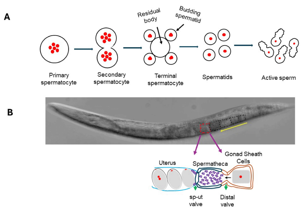
The process of spermatogenesis and fertilization in C. elegans has been diagrammatically explained in fig. 2 (refer fig. 2A & 2B respectively). The unfertilized oocyte (black dotted) enters the spermatheca through the distal valve (yellow arrow). After a few minutes in the spermatheca, the fertilized oocyte enters the uterus by spermathecal sheath cell contractions that push the cell through the spermathecal-uterine (sp-ut) valve. The fertilized eggs are stored in the uterus.
By and large,the reproductive cycle of C. elegans encompasses internal fertilization with sub-processes like sperm activation within the reproductive tract, oocyte meiotic maturation, polyspermy block to activation and degradation of selected maternal mRNAs [32,33]. Both males and hermaphrodites perform spermatogenesis during the L4 larval stage. After L4, hermaphrodite germ cells stop spermatogenesis and switch to oogenesis for the rest of their life, while males continue spermatogenesis [26]. Hermaphrodites can produce self-progeny by using their sperm but if they mate with a male, the male sperm is preferentially used because the larger male sperm gain an advantage by crawling faster to outcompete smaller hermaphrodite sperm [34]. During copulation, male sperm are ejaculated into the hermaphrodite reproductive tract. Within the hermaphrodite, the immature male sperm goes through a final maturation process known as spermiogenesis to become motile sperm capable of fertilizing the oocyte. In a hermaphrodite, sperm gets activated when the first unfertilized oocyte progresses through the spermatheca.
Like all sexually reproducing organisms, the presumptive female gametes in C. elegans also undergo meiotic maturation before fertilization [35,36]. The oocytes of most animal species arrest in meiotic prophase I and, in response to intracellular signaling, they complete meiosis (meiotic maturation). The signal that triggers oocyte maturation in C. elegans is secreted by the sperm, and is termed Major Sperm Protein [MSP] [37]. In addition to promoting oocyte maturation, MSP also induces gonadal sheath contraction, which pushes the oocyte through the spermatheca for fertilization. It has been proposed very recently that MSP might be involved in interacting oocyte components after fertilization [38]. Observations of immobile, fertilization-defective sperm that can not enter the oocyte, suggest that sperm play another regulatory role in C. elegans female meiosis. Successful fertilization of activated oocytes results in the completion of meiosis, which is followed by the fusion of male and female pronuclei and initiation of the first mitotic division [39]. It has recently been shown that pre-fertilization competition among sperm can also potentially influence the outcome of fertilization [38].
The biological model of C.elegans is not only useful in answering many fundamental questions of a living organism but also it is becoming an attractive model for studying human genetic disorders [40]. The advancement in the CRISPR-Cas9-based genome editing technique allows researchers to precisely recreate the mutation in the C. elegans gene, an orthologue of which is responsible for causing diseases in humans [41-47].
Technological mapping between robotic and biological C.elegans
The systematic process of transformation from biology to technology concerning the reproductive system of the C.elegans is the crux of the development of the prototype RoboWorm. If we scrutinize the biological paradigms of the reproductive system of C.elegans, we will be able to distinguish those into two broad verticals, namely: [a] features that can be reproducible technologically, i.e. coherent features and [b] features that need to be modulated to fit in the technology manifold, i.e. non-coherent features. The so-called ‘technology manifold’ of the biological C.elegans is nothing but the desired ensemble of RoboWorm. The features, whether biological or technological, have a direct one-to-one mapping between the representative states. This mapping is interesting to note and it gives a clear-cut idea about the so-called robotic transformation of the C.elegans worm in real-time. The major facets of the biological reproduction process of C.elegans are sperm, oocyte, MSP, and mRNAs. Considering the biological notions of these four facets a-priori, we can summarize the following one-to-one mapping for the technological counterparts: i] Sperm à Sensors of the ‘daughter’ worm robots; ii] Oocyte à Prime-movers of the ‘daughter’ worm robots; iii] MSP à Resistive circuits / Wheatstone bridge inside the sensors; iv] maternal mRNAs à fusion of sensory signal of the ‘daughter’ worm robot(s). As a corollary of [i], ‘immobile, fertilization-defective sperm’ can be mapped as a multifunctional sensor of the RoboWorm (either ‘mother’ or ‘daughter’ or both). In a nutshell, the entire mapping has a bias towards sensory augmentation of the ReWRoTE prototype. Table 1 presents a few technological parlances of the design of the prototypeCeNTER and ReWRoTE under the said two verticals.
We can observe from the above table that out of 27 features that have been listed, only 8 features are non-coherent between the biological worm and its robotic counterpart (proposed). In a way, a whooping majority (19 features:~ 70.4% ) of the features are highly coherent, which signals towards feasibility of the design for our proposed pair of RoboWorm, namely, ReWRoTE and CeNTER.
Conceptual design metrics of the proposed assistive worm robots
Design ideation for the experimental ‘Mother’~ ‘CeNTER’:
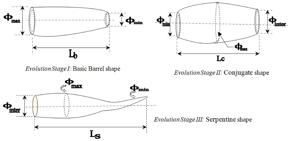
Fundamentally, the inception of ideation for the RoboWorm, ‘CeNTER’ began with the concept of a tiny single-sided tapered body, which, later on, got slightly modified to double-sided tapering of the body. The second ideation finally gets transformed into a symmetric barrel-type configuration. The initial phase of the design ideation took care of the end-diameters of the body structure of the RoboWorm ~ which has three stages, viz. minimum, maximum, and intermediate. The entire structure is conceived as a hollow body to accommodate prime-movers and a large number of tactile sensors all over the body of the RoboWorm (both outside & inside), mimicking biological C.elegans. Figure 3 schematically illustrates three evolutionary stages of ideation for the experimental ‘CeNTER’ – the body of the “mother’ RoboWorm. It also shows an artist’s view of the would-be application scenario of these two bio-robotic worms.
The first evolution stage signals a basic barrel shape of the RoboWorm, with gradually tapering out body over an ensemble length of ‘Lb’. The diameters at the two ends signify the maximum & minimum orifices (f max, f min) that the RoboForm can possess through a curved monolithic body. In contrast, we can observe three representative diameters in the second & third evolution stages~ namely, minimum diameter (f min), intermediate diameter ((f inter) & maximum diameter ((f max). While the second-stage evolution of the design-ideation leads to a conjugate curved body for the roboworm CeNTER-mother over an ensemble stretch (‘Lc’), the third evolution is realized through a serpentine shape of the robowrorm. It may be noted that we have conceptualized an extended tail of the RoboForm for some specific purpose, resembling biological C.elegans to a large extent. Accordingly, the ensemble length of the third evolutionary ideaton (‘Ls’) is much larger than ‘Lc’ or ‘Lb’.
Ideation and Analytics of ‘mother’ and ‘daughter’ ~ ‘ReWRoTE’:
The fundamental impetus behind the conceptualization of the Mother-Daughter Worm Robot (‘ReWRoTE’) is to have two semi-identical robotic systems, viz, ‘mother’ & ‘daughter(s)’. Both of these groups are equally important from the point of view of technology as well as biological parlances. We have extended the design ideation of the third-stage evolution of the experimental RoboForm, CeNTER, viz. serpentine structure for the design of the ReWRoTE-mother. Barring the external shape, the important technological paradigm of ReWRoTE was the ‘reproductive sack’ that was conceptualized to house the ‘daughter (s)’. The basic thought process for designing the unit was borrowed from the physiological aspects of C.elegans; however, the same was modified to a requisite extent for finetuning the engineering design. The conceptual bridging between the biological framework of the C.elegans worm and its gradual transformation towards an engineering (robotic) system is illustrated through an artist’s view in Figure 4. The figure shows the concept of ‘reproductive sack’ for the prototype ReWRoTE and the nascent process of ‘release’ (ejection) of ‘daughter’ worm(s) from ‘mother’ over a pre-fixed elevated datum. It may be noted that both ‘mother’ & ‘daughter (s)’ should share the common datum (horizontal plane) to ensure better stability of the dual system in real-time operations. However, if the situation demands, ‘mother’ can be at a slightly elevated surface, as in the case of Figure 4. The process of ejection of ‘daughters’ is finite, and fundamentally it is related to omnidirectional rotation and/or twist of the ‘daughters’ in 3D space. This self-rotation of the ReWRoTE-daughters can be around any axes (X, Y, Z) at random. The ensemble of the prototype reproductive worn robot has been conceptualized in a tapered torpedo-like structure that has a close resemblance with C.elegans, having three distinguishable units, e.g. ‘mouth’, ‘body’ & ‘tail’. We call this structure ‘Mother’ ReWRoTE as it houses the ‘Reproductive Sack’ (RS: refer ‘D’ of Figure 4) having a tailor-made design. The reproductive sack carries a pre-fixed number of ‘Daughter’ ReWRoTEs, ‘{Ci}’, I = 2,3,4…n. It may be noted that the geometry of the central axis of the ReWRoTE-Mother is crucial because it governs the location of the ejection-point, ‘E’. The process of ejection of the ‘daughters’ is interesting~ primarily it depends on the location of the ‘mother’. In case the ‘mother’ ReWRoTE is positioned above the datum plane, then the ejection process will involve jerky movements (of the ‘daughters’) with rotation. The complementary aspect of the ejection process of the ‘daughters’ happens with mild to severe vibration as it is essentially a free fall under gravity.
The ‘daughter(s)’ of the prototype ReWRoTE will be designed in the form of ultra-miniature crawling robots, having tiny legs (2 nos.) and one motor (servo or step-servo) for actuation. As conceived in Figure 4, ReWRoTE-daughters will be housed inside the ‘mother’ in a matrix layout. This layout can be circular or square ~ with a pre-fixed dimension/rank of the matrix. The ‘mother’ ReWRoTE will have a mouth & tail as per the standard biological configuration of C.elegans, but its reproductive sack will be comparatively larger and can accommodate a total of ‘K’ no. of ‘daughters’ inside the capsule. It may be noted that the ‘daughters’ once released from the body of the ‘mother’ will be independent and self-sufficient for any robotic motion, e.g. crawling, grazing, etc., i.e. various locomotions on a horizontal plane. The drive motor of the ReWRoTE-daughter will get energized as soon as it gets stabilized over the horizontal datum, post-spiraling motion due to ejection. Subsequently, its locomotion will commence over the datum plane ~ however, such locomotions of the ‘daughters’ will not be centrally co-ordinated as per the design as of now. The mechanism of ‘release’ of the ‘ReWRoTE-daughters’ will be sequential, with the help of the ‘mother’ (unlike biological C.elegans). The ‘daughter’ ReWRoTEs will be autonomous, via a wi-fi connection with the ‘mother’.
Design for actuation of the mother-daughter worm robot
The biological C.elegans performs its locomotion by gradual elongation and contraction of its internal physiological systems (in the form of internal force). An engineering parallel for this motion can be realized through the application of constant pulling force at a pre-assigned location of the body of the CeNTER or REWRoTE. To replicate this natural process of locomotion (via initial slow traversal followed by perpetual finite-magnitude linear movement) in the robotic system, we need to plan for the following stages of actuation for the ReWRoTE-mother, viz.: Stage I: Initiation of rolling; Stage II: Initiation of micro-translation; Stage III: Application of external forcing and Stage IV: Incipient locomotion. However, this actuation protocol of ReWRoTE-mother will not be applicable for the ‘daughter(s)’, because the locomotion of the ReWRoTE-daughter is not self-generated. The ReWRoTE-daughter(s) will be pushed through a novel Pusher Mechanism (PM) that will produce jerks/vibration to the Reproductive Sack (RS). With this backdrop, we will now detail the variations and subtle features of the design for actuation for the ‘mother’ and ‘daughter’ ReWRoTE separately in the following sub-sections.
Design for actuation of the ‘Mother’ worm robot:
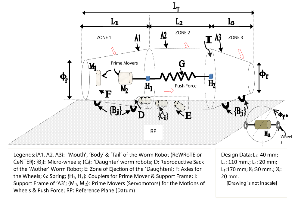
Conceptually, the torpedo-like body of ReWRoTE-mother and that of CeNTER has been divided into three ‘zones’, out of which two end-zones will be ‘active’ while the middle zone is ‘passive’. The two active zones will be separated by a mechanical spring. These three zones will be dimensionally dissimilar and those will represent the front, middle & back sides of the worm robot respectively. Placed in-between, the spring will have a rigid connection with these two zones. Each of the front & rear zones of the prototype ReWRoTE-mother or CeNTER will have two pairs of micro-wheels (i.e. total of 8 nos.) for easy locomotion, namely, rotation as well as translation over the horizontal surface in the agricultural field. Figure 5 shows the ensemble exterior layout of the RoboWorm with the demarcation of the ‘zones’, led by the motion analogy for its biological counterpart. We have conceptualized two ‘sources’ of motion-generators (prime-movers) for i] perpetual rotation of the worm robot and ii] translatory motion & pushing force function for the internal spring. It may be noted that the pushing force for the spring indirectly helps the worm robot to move forward at a slow pace. In a way, our design will help realize both rotations as well as translation (limping) of the ReWRoTE-mother over a finite time-period. It may be noted that the prototype CeNTER will not have any reproductive sack (refer to ‘D’ of Figure 5); other than this, the rest of the mechanism as well as the power transmission strategy will remain the same.
The basic triad responsible for the generation & subsequent translation of the motion for ReWRoTE-mother is {M1, M2, G}. While the prime mover ‘M1’ is designed for the production of rotational motion the other one, ‘M2’ is used for the generation of push force through the attached spring, ‘G’, and the couplers {H1, H2}. It may be noted that ‘M1’ is selected as a bi-directional type so that the rotary motion can be transferred easily to the pair of wheels at the front-end of the body of either ReWRoTE or CeNTER via the axles ‘F’. Although the frontal pair of wheels are positively powered directly from ‘M1’, the rest 3 pairs of wheels (1 pair on the frontal side & the other 2 pairs at the tail-end) are essentially non-powered type, i.e. castors. Nonetheless, the 2 pairs of wheels at the tail-end will have sufficient extra translatory motion under the spring force, generated at zone 2. We may note that only one no. wheel is shown in Figure 5 out of each pair, to have better clarity on the actuation mechanism. The inset of Figure 5 illustrates the physical assembly of the driving wheels with ‘M1’ (on both sides of zone 1). The diameter of the particular cross-section in zone 1 where the prime-mover ‘M1’ is attached is represented by ‘ff*’, where ff < ff*. As a theoretical extrapolation of this paradigm, positive motions for the rear-wheels at zone 3 would have culminated in a similar scenario of wheel assembly with fr < fr*. Along with the motion signature, it is wiser to look at the ensemble dimensions of the prototype ReWRoTE-mother ~ such as total length ‘LT’ (170 mm.), frontal diameter ‘ff’ (30 mm.), and rear diameter ‘fr’ (20 mm.). The cross-sectional diameters of ‘zone 2’ can be deduced from geometry, considering the uniform tapering of zone 1 & zone 3. There will be a slot in ‘zone 2’ (refer to ‘E’), where ‘daughters’ will drop out from the ‘mother’ on the horizontal datum (‘RP’). The capacity of ReWRoTE-mother will be defined in terms of ‘carrying volume’ for the ‘daughters’.
Design for actuation of the ‘Daughter’ worm robot:
Daughter RoboWorms will be of identical design as that of ‘mother’, except for external dimensions. Hence, we will consider a similar torpedo-like ensemble for the ‘daughters’, with the same equal end-diameters and slightly bulged-out central zone. However, unlike ‘mother’, the central zone of the daughter ReWRoTEs will not have any extended profile; rather it will be designed sufficiently to accommodate the miniature drive motor inside. Besides, ‘daughters’ will be actuated with the help of a pair of tiny legs (refer to Figure 4). The characteristics and design features of the ‘daughters’ are an ensemble length of 20 mm. & end-diameters: 3 mm. & b] length of legs: 6 mm. It may be noted that only one micro-motor will be used for actuation as well as locomotion of the ‘daughter’, if possible (with the help of a dual-shaft motor) ~ else, two micro-motors will be used for the motion of two legs separately but with synchronization. Unlike ‘mother’, no spring-loaded internal mechanism will be used in the case of ‘daughters’. The exterior surface of the prototype ‘daughters’ will be slightly bi-tapered with the identical angle of taper at both ends, i.e. ‘Head / Mouth’ & ‘Tail’. Thus, the ensemble body of the ‘daughter’ is divided into two zones only~ this feature is a bit different from that of the ‘mother’. However, we will also adopt a right-circular type cylindrical ensemble for the body of the ‘daughters’ due to ease of manufacturing, especially for the locomotion with legs. The crucial aspect for the hardware prototyping of the ‘daughter’ is the fittment of the tiny servomotor(s) inside the hollow hub. We have designed only two legs for its locomotion~ and those will be placed centrally concerning the motor. Figure 6 shows the design for the actuation of a representative ‘daughter’ worm robot with tiny legs for two types of designs of the body.
We have conceptualized two different configurations for the ‘body of the prototype ‘daughter’ ReWRoTE, namely: cylindrical shape and uni-tapered torpedo-like shape. The actuating motor (’B’) will be housed inside the ‘body’, while the pair of miniature legs (C1, C2) will be projected out of the body. The design of the legs is unique, in the sense that these will have curved ensembles with small spherical end-pieces at each leg [refer {D1, D2}]. These spherical end-pieces are designed to have smooth contact of the legs with the datum in the course of translatory motion over the horizontal plane. It is important to note that the final translatory motion of the ‘daughter’ worm robot will be oscillatory, as the source-motion is rotary (via motor ‘B’) while the transferred motion is semi-linear (over the datum). Hence, by non-analogous motion, the resultant motion ought to be oscillatory. The primary rotational motion of the actuator (‘RB’) is generated inside the central transmission shaft (‘L’), which is responsible for its onward transmission to the pair of legs. The rotational motions in the legs, viz. {RL1, RL2} get realized through a novel mechanism, having a pentagon-shaped retainer plate at each end of ‘L’. These retainer plates [refer {P1, P2}] intake the rotary motion of the central shaft and output the same motion to the legs in an intermittent manner. The retainer plate-induced transferrence of motion has a similarity to the traditional cam-follower mechanism of motion transmission. Since the retainer plates transmit rotary motion to the legs in an intermittent fashion, the induced rotary motion of the legs will wobble in real time. Thus, the final augmented motion of the ‘daughter’ ReWRoTE will be crawling type locomotion (‘TB’) over the datum, signaling intermittence wobbling.
Final design for prototyping of the worm robots
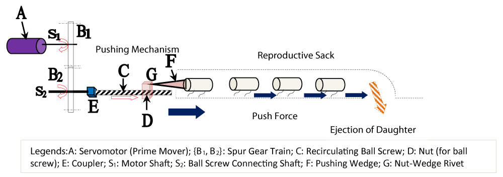
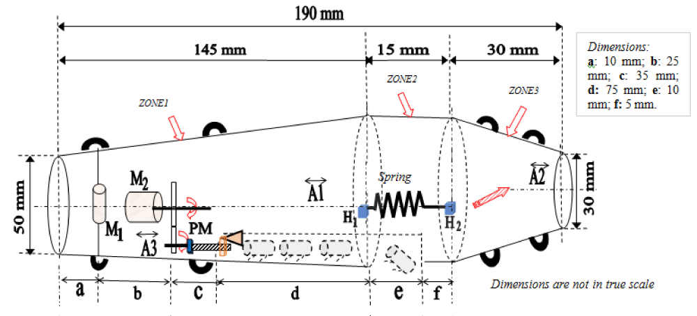
The crux of the design for our prototype RoboWorm is the design for the pusher mechanism (PM), inside the body of the ReWRoTE-mother (refer to Figure 5). The ‘daughters’ will be pushed through a novel ‘PM’ that will produce jerks/vibration to the ‘Reproductive Sack’ (RS). Hence, ‘daughters’ will move forward one-by-one in a sequential manner inside RS and eventually fall-off from the ‘Ejection Zone’ (refer to ‘E’ in Figure 5). This ‘Ejection Zone’ is nothing but a semi-wide ‘gap’ in the body of RS, measuring around 10 mm. The activation of ‘PM’ will be governed by the prime-mover, ‘M2’ (refer to Figure 5), along with a spur gear-train. It is needless to state that the entire sub-assembly of ‘PM’ will be concealed inside the body of the ReWRoTE-mother, just outside the physical disposition of ‘RS’. Figure 7 schematically shows the mechanical sub-assembly of ‘PM’ with a pictorial explanation of its actuation. The designed layout of the prototype ReWRoTE-mother carrying four daughters is presented in Figure 8.
The exterior of the prototype ReWRoTE has been designed with a bi-tapered hollow cylindrical disposition with an ensemble length of 190 mm.; while dissimilar ‘head’ & ‘tail’ diameters are 50 mm & 30 mm. respectively. The zone-wise lengths have been conceived to accommodate internal components & sub-assemblies, viz. two nos. servomotors (M1 & M2) and Pusher Mechanism (PM), besides ‘RS’. Functionally, zone 1 & zone 2 are very significant as these two zones contain all essential toolings of the robotic system. In comparison, zone 3 is a support sub-system for the locomotion of the ReWRoTE-mother. With this backdrop, lengths of the first two zones are optimized (80 mm. & 70 mm. respectively) concerning the segments, namely ‘a’, ‘b’ & ‘c’ (for zone1) and ‘d’, ‘e’ & ‘f’ (for zone2). The nucleus of the design is rooted in the disposition of the three imaginary central axes, viz. A1, A2 & A3. It may be noted that A1 is responsible for synchronizing the dispositions of i] {M1, M2}; ii] driving gear of ‘PM’ and iii] end-couplers (H1, H2) of the spring system. On the other hand, A3 is crucial is transferring the rotary motion of the driven gear of ‘PM’ through the lead screw-nut-wedge assembly for generating the required push force to dislodge the first ‘daughter’ and so on. In contrast to the functioning of A1 & A3, the central axis A2 is dedicated towards the transfer of the spring-generated push-force inside zone3 so that the ‘tail’ end of the worm robot gets an adequate boost up for the planar locomotion with the help of 4 pairs of miniature wheels or legs. However, the relative positioning of these three imaginary axes may be altered slightly considering the ease of manufacturing. We may also observe that the dimensioned layout of the ‘RS’ has been made in such a way that two ‘daughters’ can always remain inside comfortably (refer dimension of ‘d’), while the third one will be in the verge of ejection through the duct (refer dimension of ‘e’). The other important design paradigm that needs clarification is the optimal span of zone 2, precisely the ensemble length of the spring system therein. Since nearly the entire volume of ‘RS’ has been accommodated in zone 2, there is no further scope of increment of the size of ‘RS’ due to the limitation of the strength of the spring system. In that respect, the length of zone 2, i.e. 70 mm should be treated as the upper threshold of the design for manufacturing.
The lengths of zone1 & zone2 have scope for optimization, concerning the physical dimensions of the motors M1 & M2 as well as the spring. The fundamental concern of these two zones is the spacing between several engineering components. Commercial availability of the motors can be the nucleus of this optimization~ in the form of bringing in compactness. Naturally, if we can afford to have a comparatively larger length for these two zones, we can ensure smoother function for the ‘reproduction’.
We may note that there are a few open research issues so far as the design for manufacturing is concerned for the CeNTER prototype or ReWRoTE prototype~ be it ‘mother’ or ‘daughter’. There are six crucial open issues in the prototype design of the ReWRoTE-mother, viz.: i] Time of reproduction; ii] Frequency of reproduction; iii] Direction of the ejected/falling ‘daughters’; iv] Fitment of the prime-movers; v] Assembly of the Reproductive Sack & vi] Impedance Control over the reproduction process. Likewise, we can identify five open issues in the prototype design of the ReWRoTE-daughter, viz. i] Direction of ejection from ‘mother’; ii] Time of ejection; iii] Frequency or Interval between two succeding ejections; iv] Impedance Control over the ejection process & v] Locomotion of the ‘daughter’, just immediately after the ejection. It may be noted that a few of the above issues have a commonality; in other words, concepts are similar for both ‘mother’ as well as ‘daughter’ ReWRoTE. For example, the concepts of ‘reproduction’ (in the case of ‘mother’) and ‘ejection’ (in the case of ‘daughter’) have equivalent technical parlances so far as time, frequency, or impedance control is concerned. It is also true that the open research issues for both ReWRoTE-mother & ‘daughter’ are quite similar to that of the biological process of reproduction in C.elegans worm. The only difference is the realization semantics~ in the case of ReWRoTE all those metrics are evaluated in terms of technical parameters.
Experimental verification and synthesis of the design
The designs of the RoboWorm, as detailed in theprevious sections, were synthesized further for the experimental verification of the prototype. We selected the design of the ReWRoTE-daughter to begin with, because of its relative ease in manufacturing. After successful experimentation with a test-piece ‘daughter’, our efforts were channeled toward a Computer-Aided Design (CAD) model as well as a preliminary round of test hardware for the ‘mother’ worm robot. Further, we shall delineate a detailed schematic of the systemization of the RoboWorm (‘mother’-‘daughter’ duo), which can be taken as the first blue-print for the manufacturing of the prototype ReWRoTE for the intended application in the agricultural field.
Hardware development of the ‘daughter’ worm robot & test results
The hardware manifestation of the ‘daughter’ worm was conceived with a leg-type design (refer to Figure 6), having a semi-circular arch. The fabrication of the representative ‘daughter’ worm robot was achieved through 3D printing technology, wherein we have used all non-metallic semi-compliant components (except the servomotor assembly) to reduce the tare-weight. We evolved with two broad CAD models for the test-piece ‘daughter’ worm robot ~one being cylindrical type (in-line with the external ensemble of the ‘mother’) and the other one with a rectangular parallelopiped-type exterior. Finally, we zeroed over the design with a rectangular parallelopiped type exterior with slightly sculptured surfaces, having a square cross-section. Although it’s a slight deviation from the originally conceived double-barreled/cylindrical shape, we had to accept it due to limitations in manufacturing by 3D printing. The sculpturing over the external surface was made for overall aesthetics only. Figure 9 shows these two CAD iterations for the ‘daughter’ worm robot.
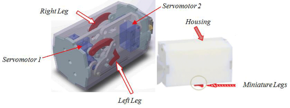
Figure 10 presents the ensemble's final transparent CAD model view of the test-piece ‘daughter’ worm robot.
The crux of the design of the ‘daughter’ worm robot is to have quieter locomotion aided by a pair of tiny legs. The disposition of the ‘daughter’ RoboWorm in final form is illustrated in Figure 10, wherein we can observe its overall external shape and exterior. Design-wise, it is unique, so far as its compact-volume disposition is concerned. After a few iterations over its design, finally we zeroed in on a square cross-section (of 20 mm. side) with an external length of 80 mm. Incidentally, this is the smallest volume that can be realized in hardware by fitting two tiny D.C. motors inside the cavity. These two motors are responsible for providing basic drive-energy for the movement of the legs.
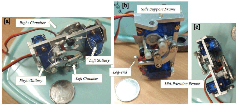
As can be seen from Figure 10, a half-way partitioning wall separates the body of the ‘daughter’ into two chambers. The prime constituent of each chamber is the leg-mechanism, which bears a special monolithic design with a very tiny part jutting out of the housing. Incidentally, that very jutting-out part of the pseudo-hidden full leg is responsible for the crawling-type locomotion over the daturm surface. The novelty of the design is such that this leg-based crawl can be accomplished over all kinds of datum~ be it horizontal or curved. It is interesting to note that there are two sculptured side-frames, respectively to provide support to the D.C. servomotors and the legs. The other important constituent member of the chambers is the D.C. servomotor assembly (with encoder), the shaft of which is directly attached to the arch-like end of the leg-mechanism. The rotary motion of the motor-shaft induces rocker-like cradle motion on the leg-mechanism at the initial arch-like end, which is transmitted further down to the exposed portion of the leg. Since the legs are disposed of symmetrically concerning the mid-partition wall, the motors are dedicated towards the locomotion of the full mechanism of the particular leg that is aimed at. The design iteration for the body of the leg-segments was zeroed within two broad verticals, as depicted in Figure 11a. The corresponding hardware development of the leg segments of the ‘daughter’ worm robot is shown in the photographic views of Figure 11b, c.
The concept design for the legs was made by considering an arch-like segment, followed by a jointed pair of straight segments (refer Figure 11a). The ensemble spread of a single leg assembly was conceived with four intermediate joints, out of which the first one is attached with the servomotor itself while the second one is fixed with a member of the partitioning frame of the chamber (not shown in Figure 11b). These are indexed as ‘Joints1’ in the zoomed view of the leg assembly (refer Figure 11c), as the motion sequences of these two joints are conjugate. The contact points of both the legs are slightly rounded, as shown in Figure 11a, so that a smooth frictional contact happens during locomotion over the horizontal plane (both straight as well as curved). The leg assemblies, viz. ‘leg1’ & ‘leg2’ are actuated separately by two servomotors, as illustrated in Figure 11b. The necessary wiring for such actuation is also made in a compact volume, as can be judged by the size-similarity notion of Figure 11b (with a small coin). The two intermediate joints of the leg assembly, viz. ‘Joint2’ & ‘Joint3’ are realized in such a way as to have a rocker-like motion of the leg in a synchronized fashion (refer to Figure 11c). These two joints are primarily responsible for the desired locomotion of the ‘legend’ segment. However, almost two-third of the ‘leg-end’ segment of each leg is internal and can’t be seen from outside because of the external enclosure (housing of the ‘daughter’ worm robot). Only one-third portion (approx.) of the ‘leg-end’ will be protruding out and those can be seen from the outside as the ‘tiny legs’. The photograph, representing the fitment of the leg assembly (refer to Figure 11b) was taken in the horizontal plane while the said task was going on. However, the final assemblies of the legs were realized in the vertical plane. It is interesting to note that because of the customized intricate curvilinear rocker-like structure of the leg mechanism, a characteristic repetitive sound will be heard during the locomotion of the device. This sound is rhythmic and continues uninterruptedly during the entire traverse of the prototype crawler.
The complete assembly of both legs of the test-piece ‘daughter’ worm robot was made with the most compact volume so that the gadget could traverse smoothly over any horizontal surface. Figure 12 illustrates three photographic views of the assembled version of the test-piece ‘daughter’ worm robot (ReWRoTE-daughter) hardware. The corresponding transparent solid model, as per Figure 10, may be referred here to identify various internal constituents. The dispositions of two important hardware components, viz. i] side support frames (2 nos.) & ii] mid-partition frame (1 no.) can be observed with clarity through the photographic views of figs. 12b & 12c respectively.
The paradigms of planar locomotion of the ReWRoTE-daughter were experimented with for different terrains, including a few non-coherent work-zones. Figure 13 shows photographic views of the slow locomotion of the ‘daughter’ using legs inside various non-metallic pipes on a horizontal surface.
The experimental paradigms for the prototype ReWRoTE-daughter were found to be satisfactory in all respects, barring sizing issues. Attempts are currently underway to fabricate a miniature version of the said ‘daughter’ that will be commensurate with the ensemble design of the RoboWorm. The prototyping of the ReWRoTE-mother will commence soon after the phase II trials of the ‘daughter’.
CAD model and test hardware of the ‘mother’ worm robot
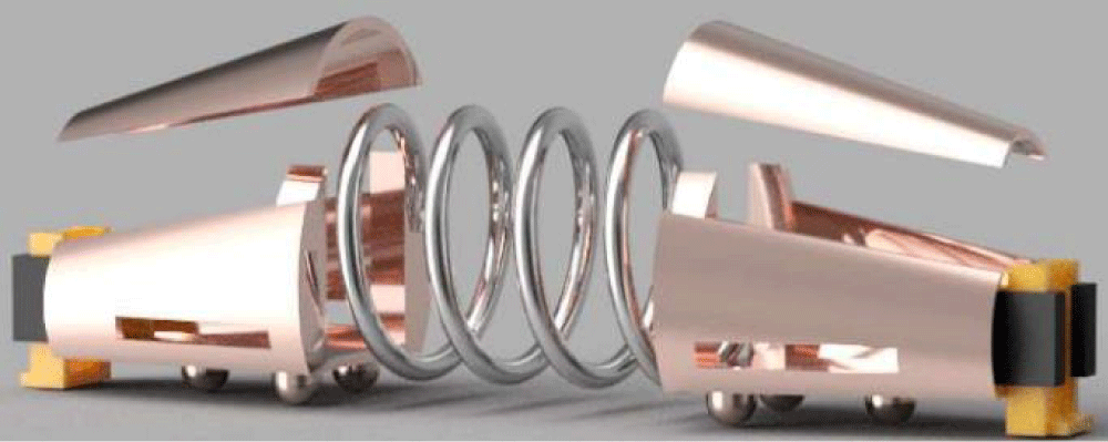
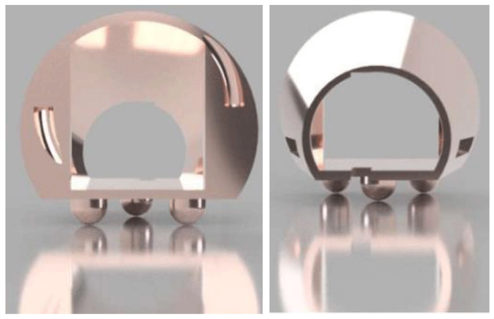
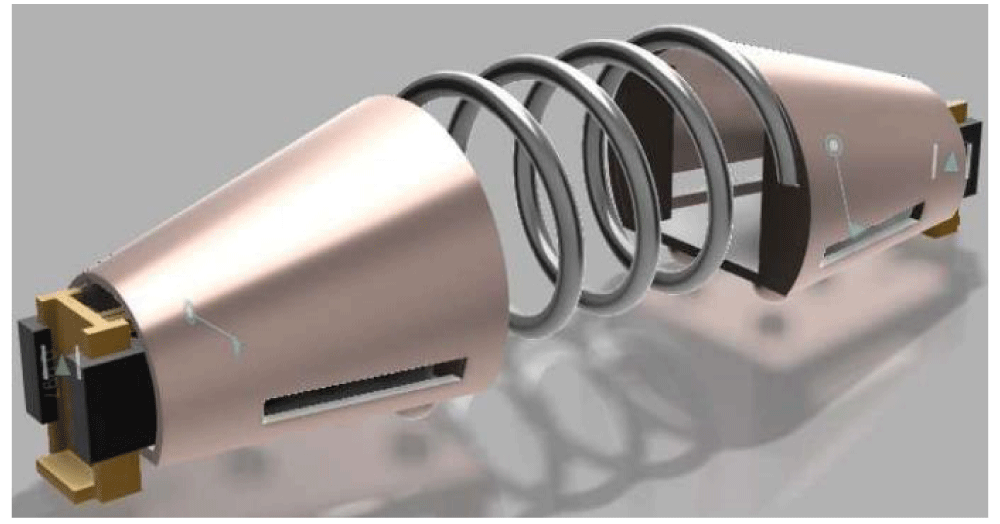
Post-design for manufacturing (refer to Figure 8), the ‘mother’ worm robot was conceptualized in detail through a CAD model. We attempted several CAD models in 3D with animation to make sure about the functionality and worthiness of its miniature ensemble. An interesting feature was unearthed by this process of CAD-based animation~ that is related to the fabrication of the Reproductive Sack of ReWRoTE-mother. Due to severe limitations of internal space, we decided to take up the manufacturing of ReWRoTE-mother as well as CeNTER in a split fashion, wherein the top portions of the housing of zone1 & zone3 were manufactured separately. This was a unique design vis-à-vis manufacturing solution, else the fitment of internal components like prime-movers (M1 & M2) & PM would have been extremely challenging. Further, the split-tye housing becomes extremely beneficial for the wiring of the entire assembly. The hardware development of ReWRoTE-mother was carried out zone-wise; i.e. separate machining for zone1 & zone2. The manufacturing of zone1 & zone3 was carried out using sheet metal forming and rapid prototyping (3D printing). We used copper as the base material for the housing due to its corrosion resistance and better electrical conductivity (for possible futuristic attributes of multi-sensory augmentation). The tiny wheels of the ‘mother’ worm robot were also fabricated using stainless steel. The spring, connecting zone1 & zone3, was modeled by maintaining typical design-codes. A pair of friction regulators (in the form of an electrical brake) was designed & modeled also to ensure the proper stopping of the worm robot. At present, the CAD design & model relies on the external forcing that we may apply to initiate the translational motion of the ‘mother’ over the horizontal surface. In general, the color of the developed working-hardware of ReWRoTE-mother was maintained as copper, to bring in good aesthetics. Figure 14 illustrates the ensemble CAD model of the ReWRoTE-mother & CeNTER, in-line with the actual manufacturing process to follow, e.g. split housing.
It may be noted here that there are two cut-portions in the CAD model: respectively in zone1 & zone3. The first cut-portion in zone 1 represents the conceptual solid model for the reproductive sack, wherein we can imagine the ejection of ‘daughter(s)’ from the area beneath the spring (under zone 2). The second cut portion under zone 3 is used to indicate the exit-pathway for the instrumentation/wiring of ensemble servomotors & sensors. Further, concerning the dimensioned schematic of Figure 8, we can visualize that zone 3 of the ReWRoTE-mother is more suitable for consolidating the instrumentation facet of the test hardware as it doesn’t contain any motion-transferring sub-assembly. The other crucial aspect of the ensemble 3D model is the fitment of the friction regulator at the designated terminals of Zone 1 & zone 3. Likewise, the design of the spring assembly is equally important as it is the prime element responsible for the transferrence of the motion of the ReWRoTE-mother in the form of locomotion on a horizontal plane. The relevant component-level CAD models, especially for the housing cavity and friction regulator as well as the CAD model of the spring sub-assembly are shown in Figure 15.
One of the major criticalities in the manufacturing as well as assemblage of the ReWRoTE-mother was the fitting of the tiny wheels. This fitment was done just after the fabrication of the casings of zone 1 & zone 3, externally, using push-fit. Figure 16 shows the photographic view of the assembled wheels (snapped from both ends of the hollow casings of zone 3).
The test-hardware of ReWRoTE-mother as well as CeNTER was assembled by following the pathway of the CAD model. However, to scrutinize the locomotion sequences of the ‘mother’ worm robot via spring actuation, we have not covered up zone 2. Hence the test-hardware, as of now, consists of full enclosure housing for zone 1 & zone 3 only, along with tiny wheels fixed in these two zones. Figure 17 shows the photographic view of the ensemble enclosure of the test-hardware of the ‘mother’ worm robot, with clear zoomed insight of the hollow cross-section of zone 3 as well as fixation of friction regulator-spring tuple at the respective places. The test-hardware is devoid of prime-movers at this hour, as our principal attention now is ensuring internal spacing for the reproductive sack and pusher mechanism to function properly.
Extension of the design of the ‘mother-daughter’ worm robot for agricultural application
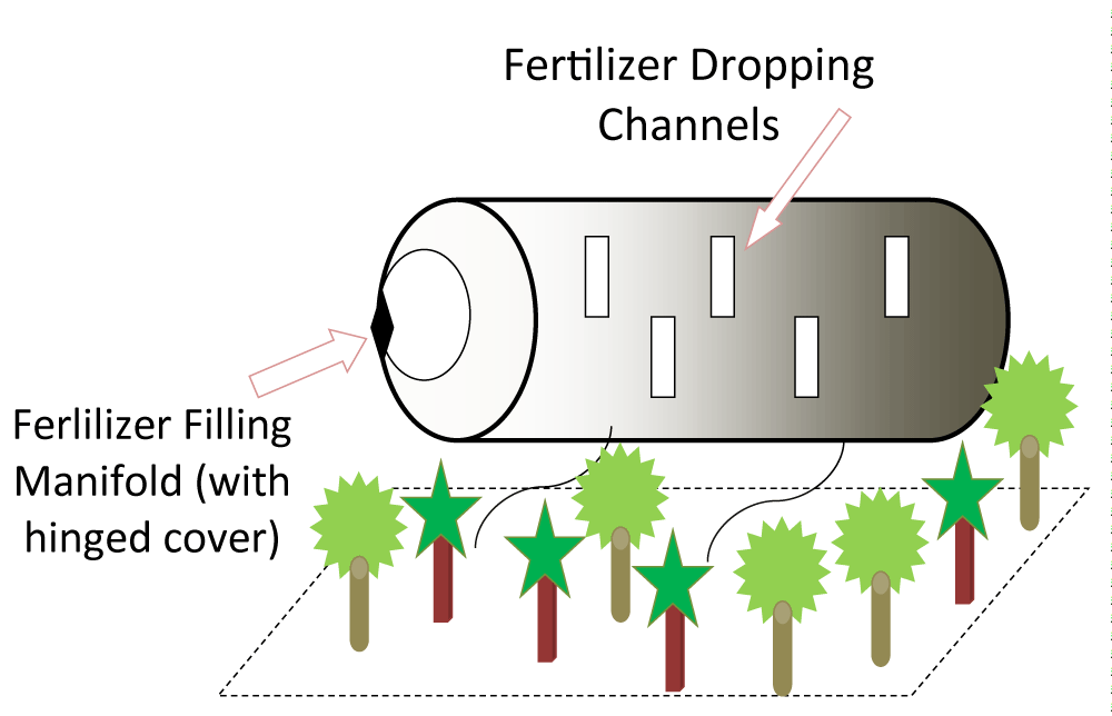
The extended manufacturing-level design for the ReWRoTE-mother as well as ‘daughter’ has been accomplished for its use in agricultural applications. We have zeroed over two specific applications of precision agriculture, more specifically, in horticulture. As the overall size, shape & mobility of the ‘mother-daughter’ worm robot are quite restricted, our intention is channelized towards the specific use of these RoboWorms for nourishing small-sized flowering and/or decorative-leaf plants that are located on the same horizontal plane. The said applications are: i] spraying of water & pesticide and ii] pouring of granular fertilizer. Both of these applications have been conceived as complimentary type, i.e. only a specific group of RoboWorm will be designated for performing a particular pre-assigned task. Based on the design features, we have earmarked ReWRoTE-mother for water & pesticide spray while ReWRoTE-daughter(s) will be responsible for the controlled pouring of fertilizer at the root-area of the plants / general soil. While the tail-end portion of the ReWRoTE-mother will be utilized for the automatic spraying of water & pesticide, granular fertilizer will be filled up to an optimum capacity inside the annular body of the ReWRoTE-daughter entirely. Both of these activities will be essentially gravity fall and because of this, it is important to design the angular tilt of the tail-end of the ReWRoTE-mother and also the in-plane stability of the ReWRoTE-daughter over its legs/wheels. Figure 18 schematically illustrates the intended agricultural application of the prototype ReWRoTE-mother.
Since the locomotion of the ReWRoTE-mother is realizable only over horizontal planar surfaces as of now, we can’t possibly use these robots for vertical farming. Nonetheless, these RoboWorms will be capable of doing the designated tasks at an elevated level, in case we can arrange for vertical lifting of the ensemble robotic system through lead screw-nut-based translatory movement. Essentially, the tasks of ‘mother’ as well as ‘daughter’ worms are co-planar motions and thus we can use the present system for actuation at an elevation on a trial basis. The spraying action, respectively from the water tank and the pesticide reservoir, will be accomplished through the ‘holes’ over the semi-cylindrical external surfaces of the said tanks. Due to gravity fall, it is expected that the desired decent of water-drops and pesticide-drops will be targeted directly over the plants beneath. Likewise, the schematic of Figure 19 illustrates the retrofitted ReWRoTE-daughter that can be deployed to pour fertilizer in granular form over the plants at the precision agriculture site.
We may notice that although gravity fall technology is exploited in the case of pouring fertilizer granules by the ‘daughter’ worm robot, there is a distinct difference in the modus operandi. Since the prototype ReWRoTE-daughter is resting on the horizontal datum with good stability at a comparatively low height (due to its tiny legs or wheels), we can afford to have slightly larger channels for dropping granular fertilizer. Accordingly, rectangular-shaped channels are conceived for this purpose. However, unlike the case with ReWRoTE-mother, the process of filling of granular fertilizer will be carried out through a manifold at the frontal side surface of the ‘daughter’ worm robot having a hinged cover as shown in Figure 18.
To get the technical details of these two incarnations of the assistive worm robots, let us take a relook over Figure 3 and imagine the design alteration that we have conceived for the ReWRoTE-mother, as per the schematic of Figure 4. While the test-hardware of the ‘mother’ worm robot of Figure 17 is the direct consequence as well as the outcome of the concept put forward in Figure 4, we can consider the extended curvilinear tail portion of ReWRoTE-mother as per Figure 3 as a modular addendum. This additional body-segment can be interfaced to the main body of the test hardware of the ‘mother’ as & when required. This requirement will be need-specific and most importantly, based on the requirement for precision agriculture for localized treatment of plants. In other words, this addendum segment will be used for the intended purpose of spraying water & pesticide using the innovative design, as illustrated in Figure 18. Likewise, the prototype of the ReWRoTE-daughter, as seen in Figure 13, has been equipped with a novel design for continuous pouring of granular fertilizer over the plants, as depicted in Figure 18. In both of these applications under precision agriculture, we won’t be using any additional prime-mover or any intricate mechanism or hardware. With this technology backdrop, various constituent members of the refurbished ReWRoTE-mother that can be deployed to spray water & pesticide in a pre-designated horticultural field or similar suitable precision agriculture field are highlighted schematically in Figure 18, with indices for easy dissemination of technical know-how. It may be noted that the angle of ‘tilt’ of the tail-portion of the ‘mother’ worm robot is very crucial for creating the pressure-head for the gravity fall of water/pesticide droplets over the plants beneath. On the other hand, the internal cavity of the ReWRoTE-daughter will have the provision of automatic refilling of the fertilizer.
It is prudent to comment at this juncture that the output quantum of either pesticide or fertilizer, as ejectable by the ‘mother’ or ‘daughter’ worm robot will be of moderate quantity, which, in ideal situations, can be sufficient for 5 to 6 plants at one go. Hence, for a large agricultural field, we may need multiple numbers of RoboWorms to cater to the ensemble's needs simultaneously. It is expected that once the test hardware of ReWRoTE-mother as well as the first-level prototype of ReWRoTE-daughter gets standardized from the aspects of bulk manufacturing, the cost of hardware development will reduce significantly. In such situations, we can afford to deploy a bigger consortium of RoboWorms in the designated field of precision agriculture.
Wider applicability of worm robot
The prime bottleneck for the manufacturing of Robo worm is miniaturization, which needs careful attention. The summit that can be achieved in this arena is capsuling for medical applications, wherein we can imagine extremely tiny worm robots are in operation. Another interesting application of worm robots is in robotic scrubbing. The scrubber will have a circular orifice, fitted with a large number of worm robots at various orientations. The conjugate motion of those miniature worm robots will produce scrubbing action over a flat planar surface, e,g. glass, nylonn, teflon etc. In all such futuristic applications, the mechanical hardware of a ‘worm robot’ needs to be extremely tiny, with built-in dexterity and compliance. The ideal process for the manufacturing of such a small-enveloped worm robot is metal 3D printing, considering the long-lasting ruggedness of the end device. These extra-thin worm robots cater to two important design facets, viz.: a] sculptured exterior and b] ultra-thin hollow interior. Robotic technologists can dwell on design characteristics of various categories of novel Annular Worm Robot (AWR) that will be helpful for deployment under constrained workspaces for surveillance (internal inspection), agriculture, horticulture, and food processing industry.
Conclusion
The synergy between biology and technology is the current trend of research in the domain of prototyping miniature-scale robotics. Although paradigms of bionic robots have been in the fray for quite some time, the concept of agricultural robots has not been heard hitherto to the best of our knowledge. A successful culmination of the design for manufacturing such an agricultural worm-type robot followed by its prototyping will usher in a novel frontier not only in academic research but also in several application manifolds. It may be appreciated that we will need ‘mother-daugther’worm robots in such domains where moderately significant quantities of ‘daughters’ are required to work. One such prominent field of potential applications of ‘mother-daughter’ worm robots is agricultural robotics. This arena requires coherent & co-ordinated operation of ‘mother-daughter’ worm robots in real-time. Nonetheless, the crux of such deployment scenarios is essentially linked up to the in-situ requirement of multiple locomotion-enabled robots, generated out of ‘reproduction’ from the ‘mother’ worm robot. With this backdrop, our proposed design of the worm robots, inherited from the biological worm C.elegans, can be entrusted to fulfill application-specific requirements in agricultural fields towards accomplishing a co-ordinated task such as fertilizer spray or water/ pesticide injection under the aegis of precision agriculture shortly.
- Hirose S. Biologically inspired robots: Snake-like locomotors and manipulators. Oxford University Press; 1993. Available from: https://www.sciepub.com/reference/27458
- Guo Z, Mahadevan L. Limbless undulatory propulsion on land. Proc Natl Acad Sci U S A. 2008;105(9):3179-3184. Available from: https://doi.org/10.1073/pnas.0705442105
- Hirose S, Yamada H. Snake-like robots [tutorial]. IEEE Robotics Autom Mag. 2009;16(1):88-98. Available from: https://www.semanticscholar.org/paper/Snake-like-robots-%5BTutorial%5D-Hirose-Yamada/993573d78fef9fd8da099140ec15da1eda3f28cc
- Stirman JN, Crane MW, Husson SJ, Wabnig S, Schultheis C, Gottschalk A, Lu H. Real-time multimodal optical control of neurons and muscles in freely behaving Caenorhabditis elegans. Nat Methods. 2011;8(2):153-158. Available from: https://www.nature.com/articles/nmeth.1555
- Leifer A, Fang-Yen C, Gershow M, Alkema MJ, Samuel AD. Optogenetic manipulation of neural activity in freely moving Caenorhabditis elegans. Nat Methods. 2011;8(2):147. Available from: https://doi.org/10.1038/nmeth.1554
- Butler VJ, Branicky R, Yemini E, Liewald JF, Gottschalk A, Kerr AA, Chklovskii DB, Schafer WR. A consistent muscle activation strategy underlies crawling and swimming in Caenorhabditis elegans. J R Soc Interface. 2015;12(102):20140963. Available from: https://doi.org/10.1098/rsif.2014.0963
- Mehringer A. Fabricworm: A biologically-inspired robot that demonstrates structural advantages of a soft exterior for peristaltic locomotion. Master's Thesis. Department of Mechanical & Aerospace Engineering, Case Western Reserve University; 2017. Available from: https://etd.ohiolink.edu/acprod/odb_etd/ws/send_file/send?accession=case1493900162956628&disposition=inline
- Bartow A, Kapadia A, Walker ID. A contractor muscle-based continuum trunk robot. Int J Syst Appl Eng Dev. 2014;8:198–206. Available from: https://www.naun.org/main/UPress/saed/2014/a562014-124.pdf
- Eder M, Karl M, Knoll A, Riesner S. Continuum worm-like robotic mechanism with decentral control architecture. In: Proceedings of the IEEE International Conference on Automation Science and Engineering (CASE 2014); August 2014; 866-871. Available from: https://mediatum.ub.tum.de/doc/1281512/201382.pdf
- Eder M. Compliant modular worm-like robotic mechanisms with decentrally controlled fluid actuators. Doctoral Thesis, Technical University of Munich Faculty of Computer Science; 2015. Available from: https://mediatum.ub.tum.de/doc/1229913/1229913.pdf
- Palagi S, Fischer P. Bioinspired microrobots. Nat Rev Mater. 2018;3:113-124. Available from: https://www.nature.com/articles/s41578-018-0016-9
- Rus D, Tolley MT. Design, fabrication, and control of origami robots. Nat Rev Mater. 2018;3:101-112. Available from: http://dx.doi.org/10.1038/s41578-018-0009-8
- Sitti M. Miniature soft robots—Road to the clinic. Nat Rev Mater. 2018;3(6):74-75. Available from: http://dx.doi.org/10.1038/s41578-018-0001-3
- Hauser H, Ijspeert AJ, Fuchslin RM, Pfeifer R, Maass W. Towards a theoretical foundation for morphological computation with compliant bodies. Biol Cybern. 2011;105(5-6):355–370. Available from: https://doi.org/10.1007/s00422-012-0471-0
- Hauser H, Ijspeert AJ, Fuchslin RM, Pfeifer R, Maass W. The role of feedback in morphological computation with compliant bodies. Biol Cybern. 2012;106:595–613. Available from: https://doi.org/10.1007/s00422-012-0516-4
- Jones B, Walker ID. Kinematics for multisection continuum robots. IEEE Trans Robot. 2006;22:43–55. Available from: http://dx.doi.org/10.1109/TRO.2005.861458
- Webster RJ, Jones BA. Design and kinematic modeling of constant curvature continuum robots: A review. Int J Robot Res. 2010;29(13):1661-1683. Available from: https://doi.org/10.1177/0278364910368147
- Mahl T, Hildebrandt A, Sawodny O. Forward kinematics of a compliant pneumatically actuated redundant manipulator. In: Proceedings of the 7th IEEE Conference on Industrial Electronics and Applications (ICIEA); 2012; 1267-1273. Available from: https://doi.org/10.1109/ICIEA.2012.6360917
- He B, Wang Z, Li Q, Xie H, Shen R. An analytic method for the kinematics and dynamics of a multiple-backbone continuum robot. Int J Adv Robot Syst. 2013;10(1):1-13. Available from: https://doi.org/10.5772/54051
- Mahl T, Hildebrandt A, Sawodny O. A variable curvature continuum kinematics for kinematic control of the bionic handling assistant. IEEE Trans Robot. 2014;30(4):935–949. Available from: http://dx.doi.org/10.1109/TRO.2014.2314777
- Calisti M, Giorelli M, Levy G, Mazzolai B, Hochner B, Laschi C, Dario P. An octopus-inspired solution to movement and manipulation for soft robots. Bioinspir Biomim. 2011;6(3):036002. Available from: http://dx.doi.org/10.1088/1748-3182/6/3/036002
- Mazzolai B, Margheri L, Cianchetti M, Dario P, Laschi C. Soft-robotic arm inspired by the octopus: II. From artificial requirements to innovative technological solutions. Bioinspir Biomim. 2012;7(2):025005. Available from: https://doi.org/10.1088/1748-3182/7/2/025005
- Melo K, Leon J, di Zeo A, Rueda V, Roa D, Parraga M, Gonzalez D, Paez L. The Modular Snake Robot Open Project: Turning animal functions into engineering tools. In: Proceedings of the 11th IEEE International Symposium on Safety Security and Rescue Robotics (SSRR 2013); 2013; 1-6. Available from: https://ieeexplore.ieee.org/document/6719368
- Onal C, Rus D. A modular approach to soft robots. In: Proceedings of the 4th IEEE RAS EMBS International Conference on Biomedical Robotics and Biomechatronics (BioRob); 2012; 1038–1045. Available from: https://doi.org/10.1109/BioRob.2012.6290290
- Caluwaerts K, D’Haene M, Verstraeten D, Schrauwen B. Locomotion without a brain: Physical reservoir computing in tensegrity structures. Artif Life. 2013;19(1):35-66. DOI: https://doi.org/10.1162/ARTL_a_00080
- Madl JE, Herman RK. Polyploids and sex determination in Caenorhabditis elegans. Genetics. 1979;93:393-402. Available from: https://doi.org/10.1093/genetics/93.2.393
- Sulston JE, Horvitz HR. Post-embryonic cell lineages of the nematode, Caenorhabditis elegans. Dev Biol. 1977;56:110-156. Available from: https://doi.org/10.1016/0012-1606(77)90158-0
- Chisholm AD, Hardin J. Epidermal morphogenesis. WormBook: the online review of C elegans biology. 2005:1-22. Available from: https://www.ncbi.nlm.nih.gov/books/NBK19676/
- Page AP, Johnstone IL. The cuticle. WormBook: the online review of C elegans biology. 2007:1-15. Available from: https://www.ncbi.nlm.nih.gov/books/NBK19745/
- Podbilewicz B. Cell fusion. WormBook: the online review of C elegans biology. 2006:1-32. Available from: https://www.ncbi.nlm.nih.gov/books/NBK19686/
- MacLeod AR, Karn J, Brenner S. Molecular analysis of the unc-54 myosin heavy-chain gene of Caenorhabditis elegans. Nature. 1981;291:386-390. Available from: https://doi.org/10.1038/291386a0
- Horner VL, Wolfner MF. Transitioning from egg to embryo: Triggers and mechanisms of egg activation. Dev Dyn. 2008;237:527-544. Available from: https://doi.org/10.1002/dvdy.21454
- Matthew RM, Andrew S. Fertilization and the oocyte-to-embryo transition in C. elegans. BMB Rep. 2010;43:389-399. Available from: https://doi.org/10.5483/bmbrep.2010.43.6.389
- LaMunyon CW, Ward S. Larger sperm outcompete smaller sperm in the nematode Caenorhabditis elegans. Proc Biol Sci. 1998;265:1997-2002. Available from: https://doi.org/10.1098/rspb.1998.0531
- Dent JA, Smith MM, Vassilatis DK, Avery L. The genetics of ivermectin resistance in Caenorhabditis elegans. Proc Natl Acad Sci U S A. 2000;97(6):2674-2679. Available from: https://doi.org/10.1073/pnas.97.6.2674
- Robertson S, Lin R. The oocyte-to-embryo transition. Adv Exp Med Biol. 2013;757:351-372. Available from: https://doi.org/10.1007/978-1-4614-4015-4_12
- Miller MA, Nguyen VQ, Lee MH, Kosinski M, Schedl T, Caprioli RM, Greenstein D. A sperm cytoskeletal protein that signals oocyte meiotic maturation and ovulation. Science. 2001;291:2144-2147. Available from: https://doi.org/10.1126/science.1057586
- Banerjee RP, Srayko M. Sperm-specific glycogen synthase kinase 3 is required for sperm motility and the post-fertilization signal for female meiosis II in Caenorhabditis elegans. Development. 2022;149(10). Available from: https://doi.org/10.1242/dev.200229
- Ataeian M, Tegha-Dunghu J, Curtis DG, Sykes EM, Nozohourmehrabad A, Bajaj M, Cheung K, Srayko M. Maternal MEMI promotes female meiosis II in response to fertilization in Caenorhabditis elegans. Genetics. 2016;204:1461-1477. Available from: https://doi.org/10.1534/genetics.116.192997
- Kropp PA, Bauer R, Zafra I, Graham C, Golden A. Caenorhabditis elegans for rare disease modeling and drug discovery: Strategies and strengths. Dis Model Mech. 2021;14(8). Available from: https://doi.org/10.1242/dmm.049010
- Paix A, Folkmann A, Seydoux G. Precision genome editing using CRISPR-Cas9 and linear repair templates in C. elegans. Methods. 2017;121-122:86-93. Available from: https://doi.org/10.1016/j.ymeth.2017.03.023
- Mintchev S, Salerno M, Cherpillod A, Scaduto S, Paik J. A portable three-degrees-of-freedom force feedback origami robot for human-robot interactions. Nat Mach Intell. 2019;1(12):584–593. Available from: https://www.nature.com/articles/s42256-019-0125-1
- Salerno M, Paik J, Mintchev S. Ori-pixel, a multi-DoFs origami pixel for modular reconfigurable surfaces. IEEE Robot Autom Lett. 2020;5(4):6988-6995. Available from: https://doi.org/10.1109/LRA.2020.3028054
- Suzuki H, Wood RJ. Origami-inspired miniature manipulator for teleoperated microsurgery. Nat Mach Intell. 2020;2(8):437-446. Available from: https://www.nature.com/articles/s42256-020-0203-4
- Liu Y, Feng B, Cheng T, Chen Y, Liu X, Zhang J, Qu S, Yang W. Singularity analysis and solutions for the origami transmission mechanism of fast-moving untethered insect-scale robot. IEEE Trans Robot. 2024;40:777-796. Available from: https://doi.org/10.1109/TRO.2023.3338949
- Zhakypov Z, Mori K, Hosoda K, Paik J. Designing minimal and scalable insect-inspired multi-locomotion millirobots. Nature. 2019;571(7765):381-386. Available from: https://doi.org/10.1038/s41586-019-1388-8
- Nguyen XT, Calderón AA, Rigo A, Ge JZ, Pérez-Arancibia NO. SMALLBug: A 30-mg crawling robot driven by a high-frequency flexible SMA microactuator. IEEE Robot Autom Lett. 2020;5(4):6796–6803. Available from: https://ieeexplore.ieee.org/document/9165070

Article Alerts
Subscribe to our articles alerts and stay tuned.
 This work is licensed under a Creative Commons Attribution 4.0 International License.









 Save to Mendeley
