Annals of Robotics and Automation
Vibration of flexible robots: Dynamics and novel synthesis of unbounded trajectories
Debanik Roy*
Cite this as
Roy D (2023) Vibration of flexible robots: Dynamics and novel synthesis of unbounded trajectories. Ann Robot Automation 7(1): 001-019. DOI: 10.17352/ara.000016Copyright
© 2023 Roy D. This is an open-access article distributed under the terms of the Creative Commons Attribution License, which permits unrestricted use, distribution, and reproduction in any medium, provided the original author and source are credited.Flexible Robotic Systems, by and large, are prone to inherent vibration that recreates itself in several modal frequencies. This in-situ vibration in flexible robots or in any such complaint robotic unit becomes tricky so far as the control system architecture is concerned. Thus, customization of the design and firmware of higher-order flexible robots is highly challenging due to its inherent parameters related to real-time vibration. Vibration in flexible robots has been investigated hitherto from the standpoint of frequency & amplitude tuple, sidetracking the important paradigm of looping of the trajectories. This work has added a technological niche in bringing out the intrinsic dynamics of this vibration from a mathematical perspective of trajectory formation so as to understand the mechanics of spiraling loops while a flexible/compliant robotic system is vibrating under natural conditions. The analytical modeling of the said in-situ vibration has been experimented with through an indigenous single-link flexible robot, fitted with a miniature gripper.
Introduction
The field of Flexible Robotics has come out as a niche ensemble of harnessing non-linearity in dynamics of the robotic system(s) in the recent past, subsuming technological challenges. However, there are still open areas of research in various facets of understanding the in-situ vibration in flexible robotic systems, especially with respect to the formation of the spiraling trajectories during real-time operation. A near-perfect analytical model involving flexible / complaint dynamics of jointed frames is the foundation for successful real-time control of multi-degrees-of-freedom Flexible Robotic Systems (FRS) as well as Compact Compliant Robot (C2R). Many of the features and physics of motion of FRS & C2R finally get translated into a modified variety of Assistive Robotics, comprising the emerging domain of Compliant Bio-inspired Robot (CBR) (e.g., rolling-type, crawling-type, swagging-tail type, etc.). Novel robotic structures from the FRS, C2R & CBR families necessarily have low mass and very high flexibility, so we can consider the large displacement behavior of such ultra-high flexible multi-body systems during real-time modeling. This modeling is worth studying because of the successful prototyping of various pertinent robotic systems that undergo medium to large trembling under run-time conditions (often leading to instability) as well as modal vibrations with high eigen vectors.
In spite of carrying an engineering boon of possessing very low tare-weight the prime shortcoming for the practical usability of FRS is essentially linked to the perpetual trembling of its constituent members as well as the end-of-arm tooling (gripper). The source of this inherent vibration can be attributed to the internal stress/strain; however, this very vibration is structure- independent as well as design-invariant. The signature of natural vibration of FRS is quantitatively ascertained through two facets, viz. modal frequency & Eigen value. We do observe chronological built-up of trembling of the slender links of FRS and at times, shaking of the link-joint interface zone due to the multi-dimensionality of the workspace. The development of a working prototype of FRS is instrumental in bringing out the issues pertaining to its ready deployment in several social & non-manufacturing sectors. However, indigenous firmware of FRS is often customized, in order to suit the requirement for indoor assistive services, e.g., patients and elderly persons. The facets of rheology (stress-strain paradigms), randomized vibration, sensory instrumentation, and non-linear coupled dynamics are some of the paradigms that need extended research in a synergistic way.
In this paper, we will focus on two representative varieties of flexible robots, one each from the FRS & C2R family, designed and developed with complete indigenous technology. In the course of the detailing, focused references will be made to the novel prior arts of prototypes of our earlier flexible robots, developed chronologically in the past six years. We will refer to the eight indigenously-designed & developed FRS, with specific reference to the novel vibration harnessing mechanisms. Chronologically, the prototypes are titled as: 1] DDFR (Direct Drive Flexible Robot~https://youtu.be/9uNW_CERa0o); 2] FSFR-I (Flexible Shaft-driven Flexible Robot: Type I~ https://youtu.be/oJcsYMLCxzk); 3] FSFR-II (Flexible Shaft-driven Flexible Robot: Type II~ https://youtu.be/P9-FrIKBBSM); 4] PAR (Patient Assistant Robot ~ https://www.youtube.com/watch?v=Nwbt94E8Tds&t=98s); 5] FUMoR (Flexible Universal Modular Robot ~ https://youtu.be/liKWRwHfHVA); 6] Flex2R (Flexible Rotary-joint Robot); 7] SAIPAR (Sensor Augmented Intelligent Patient Assistant Robot) and 8] FlexFAR (Flexible Feeding Assistant Robot). While Flex2R is a completely manually-operated experimental robotic system, dedicated to the study of run-time vibration and its measure via force closure of grasp using a novel sensor-augmented miniaturized robotic gripper, DDFR & FUMoR are manufactured with direct-drive transmission. The rest of the prototypes are actuated with a loop-through drive mechanism, namely via flexible shaft(s). The last two prototypes (SAIPAR & FlexFAR) are at advanced stages of manufacturing. Out of these varieties of FRS, we will focus on FUMoR in this paper.
In-line with the development of the FRS-family hardware, we will delineate the working prototype of a C2R and design insight for a miniature CBR. While the prototype C2R is aimed at grasping semi-soft objects within a very compact workspace (e.g. table-top), the design of CBR is conceptualized with the fundamentals of perpetuality of the rolling motion over planar surfaces. The perpetuality of motion has been ensured through the novel design of a cam-like structure, called, a retainer ring, that utilizes the kinetic energy generated out of dynamic friction with the ground surface. The designed CBR has a gradual decrement of the external envelope with a final aim of deployment for internal inspection of co-planar pipelines of smaller orifices (~ 35 - 50 mm.). The study of inherent vibration for the tiny CBR as well as small-sized C2R needs subtle dynamic modeling in order to establish a robust control system algorithm, either under tethered or wireless communication.
Prior to the design of multi-degrees-of-freedom FRS, we must have a foolproof dynamic model that is commensurate to the expected work-output of the system [1,2]. Thus, we need to consider quantitative metrics for vibration attenuation with the help of a dynamic model before the onset of the design for manufacturing FRS [3]. Extended modeling of the spring-mass tuple has been found to be very effective in establishing a new dynamic model of FRS [4]. Several other poignant methodologies have been reported for the reduction of vibration and subsequent real-time control of the FRS [5-8]. We may appreciate that non-field trials on the real-time performance of mono-link flexible manipulators (mostly without gripper) have accurized a considerable momentum in the recent past. A majority of these flexible manipulators have been used extensively to validate a variety of novel control strategies [9-11]. Nonetheless, the grasp-based design of the multi-link FRS having near-compliant sub-assemblies as well as a miniature gripper, remains an open research domain to date.
We have investigated interesting scenarios of control dynamics for a multi-degrees-of-freedom FRS fitted with a mini-gripper [12], aided by a novel spring-structural model (for vibration signature of both manipulator-links & gripper) and strain gauge-induced model (for dynamic strain signature). Firmware of a multi-link serial-chain FRS using flexible shafts for drive motion of the joints has been developed by the author’s group [13]. The complete design set-up with modeling for real-time vibration, as well as a beta version of the hardware for a slender serial-chain three degrees-of-freedom flexible robot meant for patient assistance, is described by the author [14].
It may be stated that an experiment-based case-study of the performance of the FRS-gripper amidst in-situ vibration demands a synergistic coupling of two metrics: a] optimization of design parameters of the FRS-gripper and b] joint-space redundancy of a general serial-chain slender manipulator, such as FRS. Topology optimization-based modeling & novel hypotheses towards decision matrix for robotic grasp have been delineated [15]. On the other hand, a novel theory and analytical model for joint-space redundancy of the serial-chain slender manipulator is reported [16]. Based on these earlier accomplishments, a new theology on deformation & deflection for the time-specific adjudgment of natural frequency of vibration will be presented here.
Oscillation dynamics and subsequent control systems of single-link FRS have been investigated wherein only tip-mass was considered for the modeling (in lieu of an actual gripper) [17,18]. Damping characteristics of a single-link flexible manipulator having non-linearity as well as its stabilization pattern with respect to a specified output metric have also been reported [19]. On the other hand, various mode forms of the oscillation frequency of a planar multi-link lightweight manipulator with time-varying boundary conditions have been investigated [20]. As a matter of fact, contemporary research on the vibration dynamics of FRS took cognizance of two celebrated theories of mechanics, namely, Timoshenko Beam Theory and Euler Beam Theory. Timoshenko Beam theory addresses two major verticals so far as the deformation/deflection of engineering entities are concerned, namely: a] shear deformation and b] factors dealing with rotational bending. The dynamics of natural (free) vibration of a multi-link flexible manipulator was studied analytically using Timoshenko Beam Theory [21-23]. It was reported by the researchers that the eigenvalue problem involving the in-situ oscillation of a flexible arm is nearly identical to the solution of a ‘beam’ equation. However, the instantaneous deformation dynamics of FRS are ideally a mixed combination of ‘beam deflection’ and ‘shear deformation’. The lemma of shear deformation in a flexible hub-beam system was studied, wherein it was observed that shear deformation varies with the ratio of the length-to-equivalent diameter of the ‘beam’ in a significant manner [24]. Lyapunov and passivity techniques have been utilized in these works so as to migrate from a partial differential equation-based model to one that is more reliable and sturdy [25]. Besides modeling using a ‘beam’ configuration, paradigms such as the effect of centrifugal forces and speed of trajectories have been considered for the dynamic modeling of FRS [26]. The non-linearity in the dynamic control of FRS was transformed into a linearized dynamic model using the Lagrange-Euler method and the same was applied to a multi-link flexible manipulator after validation via trapezoidal driving torques of varying slopes but constant magnitudes [27]. The classical treatise on the computation of potential & kinetic energy element by element in order to construct the Lagrange equation for a multi-body dynamic system can be referred to in this context [28]. While one group of researchers used the well-known Lagrange-Euler-assumed mode technique [29], the other group concentrated on the modeling of constant curvature using the Euler-Lagrange formalism for a single-link manipulator [30], accepting the fact that the exact solution of the concerned dynamic equation might not exist always. However, another contemporary study reveals the insufficiency of Lagrange modeling which can lead to the possibility of developing a new dynamic model of an FRS utilizing appropriate workspace-specific mathematical tools [31]. Rao, et al. [32] aimed at solving the governing differential equations of the single-link flexible manipulators using the Galerkin method, where the solution has been approximated by a polynomial function. The paradigms of dynamic modeling of a single-link flexible manipulator with two cables have been reported also [33]. A new technique of dynamic analysis for real-time grasp synthesis of a robotic gripper has been postulated also [34].
It may be noted that the scaling parameters for any one of the models cited above, either run-time dynamics of the flexible manipulator and/or its grip, are denoted as crisp values, which can be accurate or deterministic. However, the physical parameters that are associated with the vibration of FRS are often uncertain and as a natural consequence, we need to consider dynamic modeling that is based on interval or fuzzy mathematics. The concept of ‘Fuzzy Logic’ has transcended further research and has also provided a solution for many practical difficulties in a variety of fields [35-39]. The applications of computational and fuzzy mathematics involving initial value problems have been addressed, which have much relevance to the dynamic modeling of multi-body systems [40,41]. The Eigenvalue problem in ‘the deflection dynamics of ‘the beam’ has been solved both in the crisp case as well as by implementing fuzzy uncertainty [42-44]. Although many studies pertaining to modeling go with the Euler-Bernoulli equation, such as [45], we may conclude that governing differential equations and boundary conditions thereof lead to an eigenvalue problem irrespective of the methodology invoked for solving random vibration of FRS. Systematic comprehensive modeling of run-time vibration of a prototype single-link flexible robot using a combined technique of Timoshemko Beam Theory and shear deformation has been reported by the author’s research group [46].
The paper has been organized into six sections. An overview of the fundamental modeling semantics of the perpetual vibration of serial-chain FRS is presented in the next section. Section 3 reports the paradigms of run-time vibration with inherent flexibility, with illustration and physical prototypes built (FRS & C2R). The characteristics of the run-time data on vibration analysis and related modeling of the oscillatory behavior of the FRS are presented in section 4. Section 5 addresses the preludes to the experimental investigation on run-time vibration of prototype flexible robots and finally, section 6 concludes the paper.
Perpetual vibration of flexible robots : modeling fundamentals
The most fundamental aspect of the real-time vibration of the flexible robot is the instantaneous deflection of its link(s) that can be quantified through displacement vectors. This deflection is assumed to be uniform and widespread inside the body of the link. In other words, the deflection of the link is assumed to be homogeneous and uniformly distributed over the surface as well as inside the link-body. So, fundamentally, this run-time deflection of FRS or C2R is very much an intrinsic property and it is highly dependent on the material of construction of the link. Of course, the stability of the link(s) of FRS or C2R post-vibration is always a technological issue that needs careful measurement of the stable deflection values. Hence, at the nucleus of the analytical model supporting the vibration of FRS, we will study the vector analysis of the micro-displacement of the ‘elements’ of the FRS link. This basic novel conceptual framework is represented schematically in Figures 1a,b.
The basic nature of the run-time deflection of the FRS-link is highlighted in Figure 1a, wherein the link OA is getting displaced instantaneously to the position OB, with respect to the global / home reference frame [Xg Yg Zg]. The position vectors for points ‘A’ & ‘B’ are respectively & in accordance with the zones of in-situ deflection of the link, namely, ‘Ω’ & ‘Ω∗’. It is important to note here that there is no pre-assumed trajectory of this deflection; rather we can’t predict this trajectory using mathematical tools a-priori. This is, in fact, the biggest irony for the design & run-time control of the flexible robots. Thus, the very nature of the said trajectory, indexed by needs to be ascertained only through repeated experimentations, using a range of ‘excitations’ (external force-functions). It is true that these three vectors ( ) may form a triad, which, at times, can be solved geometrically. However physical assessment of the deflection can only be made via experimental data. A large set of testings were reported on this facet by several research-groups and those do give a clear picture of the nature of this deflection in quantitative terms. The schematic of Figure 1b essentially brings out this concept of experimental variation. We can observe that a representative cross-section of the FRS-link (at the zone Ω) is zoomed in to highlight the internal fixed locations (the black dots) that undergo excitation by an external forcing function, ‘Pi’. In other words, all the elements inside a fixed cross-section/zone of the FRS-link will undergo in-situ micro-deformation but the extents of such deformations are not similar all the time. The deformed state of the said cross-section has been demarcated by the zone Ω∗ that contains the same internal elements but in deformed states. The curved line-segments of Figure 1b represents those unequal deformations of FRS-link at the element level. The modeling paradigms of the perpetual vibration of flexible robots are highly dependent on the external excitation and the corresponding forcing function(s). Thus, we can assume that a separate forcing function, ‘P*j’ is acting over the other cross-section. This variational forcing function is the key to the detailed vibration study of the FRS subsequently.
We shall now investigate another crucial aspect of the vibration model, namely, the Spring-Structural Model (SSM). The model has been conceptualized and expanded indigenously, with specific reference to serial-chain flexible manipulators. Figure 2 illustrates the so-called longitudinal syntax of the in-situ deflection of the FRS-link. We may note the presence of ‘lumped mass’ in Figure 2, which essentially symbolizes the mass of the specific cross-sectional area of the FRS-link. Nonetheless, this lumped mass can be extended to more than one cross-section as well, or in other words, the lumped mass is allowed to subsume a designated area of the FRS-link under study (for vibration). Here, the modeling of flexibility has been proposed through a tri-junction, namely coupling of spring constant (KN), viscous damping coefficient (CN), and transient amplitude factor (TN). Hence, the quantum of the final deflection of the FRS-link will be governed by the numerical values of these three parameters. The proposed SSM is quite similar to Discrete Element Modeling (DEM) which defines the interaction of an assembly of ‘disks’ or ‘spheres’, using the proposition of a ‘chain of contacts’. Likewise, we have conceptualized SSM as the inter-zonal forcing function between the segmental links of the FRS.
It is also important to state that the concept of a semi-stable datum in Figure 2 is largely imaginary unless the flexible robot is mounted over a fixed frame. For the sake of generality, we have visualized the SSM to be in slow rotation mode, i.e. the link(s) of the flexible manipulator will be subjected to some twist or slow jerking (external excitation). It is interesting to note here that several cases of SSM may appear in the real-life operation of FUMoR, such as a] linear spring with non-linear dashpot; b] non-linear spring with linear dashpot, and c] non-linear spring with non-linear dashpot.
In cases of FRS-prototypes with the standard design of links, run-time deflection of such links was assumed small hitherto, so that the link transformation could be composed of summation of assumed link shapes. Thus, kinematics of both the rotary-joint motion and the link deflection used to be described by usual 4 x 4 transformation matrices. This proposition might be valid for single-arm type FRS having the standard configuration, as most of the hardware is made up of metallic materials, e.g. Mild Steel or Aluminium. Naturally, the ‘quantum of deflection’ in those single-link FRSs used to be negligible because of the structural rigidity; in fact, the major chunk of such deflection could be sourced to the slenderness of the links only. That’s precisely why erstwhile researchers could afford to assume ‘small’ deflections of the FRS-link(s). However, with the advent of a large variety of non-metallic materials (e.g. CFRP, ABS, Nylon), piggybacked with advanced manufacturing processes such as Rapid prototyping, we can no longer be able to assume ‘small’ deflection(s) of FRS-link(s). In fact, run-time deflections of these non-metallic links are substantial even at lower mode-shapes. In fact, traditional kinematic & dynamic models are somewhat simple and those can no longer be adequate to improve the grasp performance of the FRS in critical applications. Improvement in performance of the majority of the flexible robotic systems does require the ability to model the system behavior with improved accuracy. While the foundation phase of research in FRS completely gets engulfed by the proposition of full linear dynamics (lumped mass & spring: a linear model of elasticity), later on, modeling for limited flexibility was put forward using the lemma of limited distributed dynamics. True representation for modal frequencies and flexibility thereof was brought in through planar non-linear model(s) that finally culminated into distributed frequency-domain analysis via truncated modal models of non-linear spatial dynamics. With this backdrop, new non-linear equations of motion are developed for the arms of our FRS-prototypes, consisting of rotary joints that connect parts of the links. In our model, deflection transformation is realized through a 4x4 transformation matrix, representing both joint as well as deflected motion of the link-joint interfaces. The said deflection transformation is mathematically represented in terms of the summation of ‘modal shapes’.
Run-time vibration under inherent flexibility
Customization of the design and firmware of higher-order flexible robots is highly challenging due to its inherent parameters related to run-time vibration. Although the design ensemble of serial-chain FRS has been refined over the years with novel research paradigms, it is still crucial to study the niche for perpetual vibration, especially in flexible robots that have highly compliant links. In our endeavor of designing & prototyping various kinds of serial-chain FRS, we have observed that a flexible robot with a gooseneck-styled slender link is dynamically more challenging than the same having a standard cross-section hollow cylindrical link. We made an experimental investigation towards ascertaining the most optimal cross-section of the FRS-link out of three possible alternatives, viz. circular, rectangular & square. Likewise, another crucial factor in judging run-time vibration is the ensemble morphology of the FRS-link: be it external or internal. While external metrics can be with varieties of links having either straight or tapered or stepped cross-sections, we can realize the physical hardware of the flexible robot with two internal facets, viz., solid or hollow cross-sections. Naturally, the dynamics of FRS will alter significantly as per the finalized design ensemble as discussed above. The other crucial parameter for vibration characterization is the material of fabrication of the FRS-link(s), which by & large, gets manifested through type of material (preferably non-metallic), density & Young’s Modulus.
We have found from the chronological development of seven hardware of FRS that run-time vibration differs significantly based on the joint paradigms. This facet will not be apparent for mono-link flexible robots because joint dynamics is the least in such cases, except for the rotational motion of the base joint. In our first prototype, christened as, ‘Direct-Drive Flexible Robot’ (DDFR), we have observed the influence of the mating pairs of the three revolute joints therein. Unlike the traditional way of fabricating revolute joints around a vertical axis, in DDFR we opted for revolute joints between two adjacent links in side-by-side alignment. However, in our subsequent prototypes, namely, ‘Flexible Shaft-Driven Flexible Robots’ (FSFR-I & II) we used the vertical alignment of the revolute joints (refer: https://youtu.be/P9-FrIKBBSM). The run-time vibration gets heavily influenced by the joint sub-assembly that partakes link-joint interface as well. The concept of high-efficiency revolute joint sub-assembly was used in a well-acclaimed prototype FRS of ours, namely, ‘Patient Assistant Robot–Beta version’ (PARv1.0): its performance including vibration harnessing techniques can be viewed at: https://www.youtube.com/watch?v=Nwbt94E8Tds&t=98s. In a nutshell, the design features of a typical revolute joint of FRS can be grouped on the basis of its type, mating pairs, alignment, and sub-assembly so far as vibration abetment is concerned. The other ancillary parameters that might have some influence over the harnessing of in-situ perpetual vibration of FRS are the drive mechanism and end-of-arm attachment. We have tried both types of drive mechanisms that are possible in FRS, viz. direct-to-joint (e.g. DDFR) and via flexible shaft (e.g. FSFR-I, FSFR-II, PARv1.0). Flexible shaft-driven FRS is slightly robust so far as vibration attenuation is concerned and on the basis of this experience, we have finalized the design for manufacturing for our next two FRS-hardware, namely, Sensor-Augmented Intelligent Patient Assistant Robot: SAIPAR and Flexible Feeding Assistance Robot: FlexFAR, with multiple indigenously-manufactured flexible shafts. Like the drive mechanism, we have also noticed moderate to heavy variation in vibration signature for FRS with different kinds of end-of-arm tooling, like tip-mass, miniature gripper & end-effector.
The conceptual framework of the single-degree-of-freedom flexible robot with the slender gooseneck-styled flexible link is illustrated in Figure 3a. The corresponding solid model through Computer Aided Design (CAD) is shown in Figure 3b. The mapping of the legends between the two figures may be noted.
It is crucial to note that the vibration and/or rheological features of the FRS do alter under two situations of end-of-arm attachment, viz. end-/tip-mass vis-à-vis a mini-gripper (at the distal link of the FRS). With the advent of our expertise in prototyping multi-link FRS, we have brought in the concept of modularity in the hardware. The prototype development of the flexible robot having CAD view as that shown above (Figure 3b) has been accomplished with the coherence of prior arts and allied exposure through troubleshooting on earlier prototypes. Figure 4 presents the final working-level prototype of the said flexible robot, entitled, Flexible Universal Modular Robot (FUMoR). FUMoR is the first on this kind of mono-link flexible modular robot that uses a non-standard geometry of the link, namely, gooseneck-styled. The most pragmatic design aspect of FUMoRv1.0 is attributed to the gooseneck-styled link vis-à-vis the standard configuration of slender links of other types of FRS. The prototype FUMoR has one gooseneck link, one custom-built revolute joint, end-connectors & adapters for fitting with the tripod base at one end, and a miniature gripper at the other end. The functionalities and grasp performance of FUMoR can be visualized at: https://youtu.be/liKWRwHfHVA
It is to be noted here that due to variation in the cross-section of the gooseneck link of FUMoRv1.0, the spring-dashpot model of vibration quantification (Figure 2) in each ‘segment’ of the gooseneck link will not be similar to one another. This dissimilarity in segments is essentially due to the variation in the profile of the outer surface of the gooseneck link. In standard flexible robots, e.g. DDFR, FSFR, and PAR we do not encounter this sort of variation in the profile of the link. Although at times we can design for a tapered cross-section of the FRS-link; that won’t alter the characteristics of the spring-dashpot model of run-time vibration. The gross nature of vibration of FUMoR is highly perpetual because of its inherent design and it can be explained pictorially through the schematic plot of Figure 5, in the form of perpetual cycles of oscillations (under external excitation).
From the operational aspect of the control system of FRS, we need to pay attention to two ensemble amplitudes, viz. a] the ‘final’ amplitude of oscillation (after the grasp is over), i.e. {λfinal}e and b] the ‘maximum’ amplitude of oscillation (occurring at any intermediate cycle, from the 1st. to the nth), i.e. {λmax}e. We shall present the analytical lemma for these two amplitudes of oscillations in the next section.
The other important aspect of the spring-dashpot model is related to the inherent flexibility in transverse/radial direction. This sort of flexibility does arise in gooseneck-styled links due to the twisting nature of the material and /or manufacturing process. This twisting enhances the jerking in the system and it percolates into the infinitesimal cross-sections of the link as well. This micro-variation of the cross-sections can be estimated theoretically through Independent Twin-Spring Architecture (ITSA). Figure 6 schematically illustrates the concept of ITSA, with reference to twisting cross-sections of FUMoR-link.
It may be noted that different transverse planes, namely, A1-A1’, A2-A2’,…., Aj-Aj’,…and finally, An-An’ have been constructed to segregate different cross-sections of the hollow tapered gooseneck link of FUMoR, as depicted in Figure 6 above. We can observe slight twisting with respect to the Newtonian Co-ordinates {X, Y, Z} in a few of these cross-sections and accordingly, local co-ordinates at each of these cross-sections (shown in red color in the diagram) bear the signature of the said twisting. Now, we need to be careful regarding the modeling of this twisting, which will get added to the natural vibration of the system. Since twisting the gooseneck link is a natural process, we will use the spring system model to showcase the vibration thereof. However, the so-called Omni directionality of the twist can only be modeled optimally through the conceptualization of two springs, working in quadrature. We have christened this novel model as: ‘Independent Twin-Spring Architecture’, which is entrusted to capture micro-vibrations in the gooseneck cross-sections. Theoretically speaking, ITSA can have different configurations as well, wherein the twin spring will have included an angle other than 900. Nonetheless, the conceptual framework of transverse flexibility is ideal for modeling the vibration characteristics of FUMoR. Figure 7 presents the ensemble disposition of transverse flexibility.
The criteria for selecting an appropriate model for the purpose of synthesizing the real-time vibration of FRS will thus be as follows: a] orientation of the cross-section with respect to the vertical axis or plane of vibration; b] deflection of the cross-section with respect to the vertical axis and c] inherent flexibility or elasticity in the radial direction. Out of these three criteria, we need to dwell more on ‘b’, namely the semantics of run-time deflection of the cross-section, which has many interesting theoretical paradigms pertaining to oscillatory motions. In fact, the mathematical facets of such oscillations are universal to both FRS and C2R. The common thread for this modeling is the non-linear dynamics of the oscillatory system with or without the presence of damping. The ideation of boundedness of the dynamic equation and stability of the oscillatory system (FRS or C2R) are two vital aspects of such modeling. We will bring out the conceptual framework and novel modeling of this oscillatory motion, as applicable to our prototypes, in the next section.
We will now study the prototype hardware of a novel C2R, which has been designed with two focused intentions, viz.: a] highly slender & low tare-weight links and b] adaption to multiple grippers having design variations in the jaws. Both of these objectives have been successfully accomplished through our novel hardware. Like FUMoR or for that matter any other FRS, perpetual vibration is a concern here too, which was studied in depth before the grasp. Figure 8 shows the photographic views of the prototype C2R in working postures using two different grippers for the grasp of a semi-soft object.
It is important to note that in all experiments with the prototype C2R selection of the rotational speed of the joint-motor(s) becomes instrumental so far as the proper functioning of the control system is concerned, amidst slow jerking/vibration of the system. Object manipulation (by the gripper-jaws) was carried out with a slow speed at the wrist, which is approximately 25% of the base rotation speed (~ 3 - 4 rpm). We have also incorporated a time delay between every incremental angle of rotation so as to ensure jerk-free movement of the wrist & gripper assembly during task execution. The customized program module has been made interactive in order to systemize multiple grippers. In order to combat the run-time vibration of the prototype C2R, two posture-driven strategies have been implemented in order to evolve an effective control strategy. This novel control semantics has become a boon for the prototype C2R, wherein objects are being grasped through two modes, namely: a] in-plane grasping and b] off-plane lifting. Both of these two strategies have been found to be very effective in minimizing the system trembling or run-time vibration. The real-time performance of this prototype C2R can be viewed at: https://www.youtube.com/watch?v=lpkQ8JM1-rY and https://www.youtube.com/watch?v=K6OZYSr-8pk.
Source identification and characteristics of run-time data on vibration
A] Towards identification of source of vibration: Beam-theory re-visited Contrary to the traditional proposition of non-linear analysis of in-situ deflection of FRS or CBR, the alternate approximations towards solving the said transient Finite Element (FE) analysis involve the definition of a set of generalized deformation parameters, degenerated at the element level or the formulation of 3D degenerated beam elements. Another formulation in this context consists of deriving the ‘beam equation’ for the in-situ vibration directly from a 3D non-linear theory that accounts for ensemble finite rotations of the joints of the FRS or CBR. Nonetheless, the solution of any 3D non-linear model necessarily calls for assumptions and therefore, we need to introduce approximate beam kinematics in the said dynamics model of vibration as assumptions. This transformed 3D non-linear theory with approximate beam kinematics leads to the so-called concept of ‘Geometrically Exact Beam Theory (GEBT)’. New formulations of run-time dynamics for our prototype FRS & CBR have been achieved by successfully adapting the basic lemma of GEBT.
It is prudent and computationally or scientifically perfect to employ an updated Lagrangian formulation for the said novel modeling using GEBT, wherein vibration-induced rotations of the flexible/compliant systems are described as increments with respect to the previous configuration. The resulting mathematical formulation becomes a set of Eulerian transformations with regard to the rotational degrees-of-freedom of the specific flexible system. Our novel mathematical formulae allow, on the other hand, a relatively simple derivation of fully linearized static and dynamic operators, but, on the other hand, these operators are non-symmetric in a general case of FRS or CBR. Nonetheless, ‘symmetry’ is shown to be recovered at equilibrium post-vibration so far as statics of the vibrating bodies are concerned, provided appropriate conditions of conservativity of external loads to these flexible robots are respected.
We have used the celebrated Euler-Bernoulli beam theory for the FE-based dynamic analysis of the prototype FUMoR. We have assumed that the end-displacement of the FRS, namely, that of the pair of jaws of the miniature gripper can be separated into two parts, respectively dependent on position and time as shown below:
Where, w(x,t): overall displacement of the gripper-jaws; Ʌ(x): component of the displacement as a function of position and Ψ(t): component of the displacement as a function of time. The governing equation that was used for estimating these two components of displacement under FEA to ensure simple harmonic motion is presented below:
Where, E: Young’s modulus of the material; I: Moment of inertia of the ‘beam’ (gripper-jaw / body); A: Cross-sectional area of the ‘beam’; k: Linear mass density of the ‘beam’ (= ρA; ρ: material density); ω: Frequency of vibration of the ‘beam’. Now, segregation of the position variable of eqn. 2 will lead to the following FE-equation:
where, {C1,..C4} are constants and (3b)
Likewise, we can get the following extraction of eqn. 2 for the time variable, as used in FE-analysis:
The FE-analysis-based solution for eqn. 4 will be:
where, C5 and C6 are constants.
Finally, the combined FE-equation for the displacement of the gripper-jaw /body becomes:
where, the constants {C1, C2, C3, C4} can be obtained from the boundary conditions and {C5, C6} are obtainable from the initial conditions under the FE-analysis.
The above formulation proves that an appropriate description of the flexible members in many cases requires the use of ‘beam’ formalism that incorporates inherent non-linear effects of the run-time vibration of such flexible / complaint robotic gadgets in a systematic manner. ‘Geometric Stiffening’ is one such source of non-linearity that can be studied extensively in the case of FRS. Effective modeling of our prototype FRS was carried out by incorporating the theory of geometric stiffening. It is, therefore, essential to rely upon a tailor-made GEBT, which should have important kinematic assumptions, like i] the flexible beam will be straight initially; ii] cross-sections of the beam remain in plane and do not deform during elastic deformation of the flexible frame (unless it is a soft flexible member); iii] the neutral axis of the flexible beam undergoes shear deformation and iv] the rotational kinetic energy of the cross-sections is taken into account (especially true for CBR). In a nutshell, we need to consider the episodes of turn, twist, and deflection of the segmented infinitesimal cross-section(s) of the flexible link/body/member, by defining the coordinates of any arbitrary point inside the said infinitesimal cross-section(s). It is important to note that the positional paradigm of any point inside the cross-section will have an additional vector component due to the inherent vibration of the FRS or at times, CBR. However, this additional vector will be manifested in those two Cartesian axes that are in quadrature to the third axis, representing the direction of in-plane as well as in-situ vibration.
B] Run-time vibration: Novel paradigm of oscillatory spirals Let us now take a re-look over eqn. 6 from a slightly different perspective. The displacement equation, so model, can also have another incarnation that symbolizes the oscillatory behavior of the FRS or C2R. This analysis is more akin to constructing the first recurrence map (Poincare Map) of the continuous dynamical system having a specific lower dimensional subspace that matches well with the perpetual oscillation of the FRS in real time. Irrespective of the design of such FRS or C2R, recurrence maps can be generated for any type of flexible/compliant robotic system: be it with the single-link system (like FUMoR) or with multiple degrees of freedom. Traditionally, recurrence maps are used to ascertain the stability or boundedness of the dynamic system and in most practical situations we compare such maps, such as displacement versus velocity plots or plots with displacements in two quadrature axes. In cases of FRS or C2R, the said recurrence nap takes the shape of a ‘basic spiral’ that recreates itself as the time of operation progresses. The locus of this special is the root cause of the oscillation. Figure 9 schematically illustrates the concept of basic spiral in reference to the oscillatory motion of the FRS-links / gripper and body-segments of C2R, post-deflection. The spiral is plotted as the instantaneous variation of oscillatory velocity with respect to the distance from the neutral axis of the FRS-link. The pattern of the said spiral is typical in the case of forced vibration without damping.
The nucleus of any oscillatory motion of FRS or C2R is the incipient deformation and subsequent deflection of the neutral axis of the link of such a flexible system. This deformation can take place in two predominant pathways; out of which one incarnation is illustrated in Figure 9a that is typical of FUMoR. The representative link of FUMoR is shown in the Figure: under the ‘underformed’ as well as ‘deformed’ state. The ‘double buldge’ of the neutral axis may be noted, which is the characteristic feature of a gooseneck-styled link. The analytical framework of this double buldge type deformation of the neutral axis is explained through the formation of a ‘basic spiral’ as shown in Figure 9b. The basic spiral is plotted as a variation of oscillatory velocity ( ) versus the magnitude of the deflection (measured as the distance from the neutral axis of the flexible link: x) in real-time. The spiral starts from ‘A’, which is a representative point on the lowermost fiber of the flexible link, symbolizing a negative distance from the neutral axis (say, -xA). The oscillation starts setting in along the curved pathway (AE) and attains the maiden oscillatory velocity (+ve) at ‘E’ (say, E, ), corresponding to a location ‘B’ on the neutral axis where x = 0. The oscillation sets in now and the basic spiral traverses through location ‘C’, symbolizing the uppermost fiber of the flexible link. Incidentally, locations ‘A’ & ‘C’ are equidistant from the neutral axis, or in other words, |-xA| = |xC|. As the oscillatory motion passes over ‘C’ and moves again towards the upper-side of the neutral axis it attains an oscillatory velocity in the reverse direction at ‘E*’ (say, - ). This pattern continues till ‘D’, which is again on the neutral axis (x = 0); however, jerky oscillation begins along the curved pathway DF. The flexible link attains a positive jerky oscillation velocity at ‘F’ (say, : numerically, |BF|) that subsequently becomes the gateway of the full-fledged oscillatory velocity of the flexible link with vigorous vibration as time progresses. This pathway is nearly exponential; with a generic marker ‘G’ that signifies substantial vibrational amplitude, as the system does not have any viscous damping.
It may be noted here that the natural frequency of vibration of the flexible link/system is directly proportional to the run-time oscillatory acceleration. The theoretical estimation of the pattern of such acceleration can be deduced from the basic spiral (Figure 9b). We assume linear oscillatory acceleration here that follows an approximately straight line at some sectors of the basic spiral. However, the full-fledged vibration, especially under undamped conditions, will have exponential growth of the oscillatory acceleration. Figure 10 analytically depicts the basic sprial for the oscillatory acceleration of the flexible link. As illustrated in Figure 9b, the pattern of the oscillatory acceleration ( ) in Figure 10 remains approximately the same, except AE & DF sectors. While AE signifies maiden oscillatory acceleration (+ve), DF represents the same under jerky conditions, prior to the setting of vigorous oscillation. Analytically, at ‘B’: x = 0 but ≠ 0, bearing two values, viz. and - . Likewise, at locations ‘A’, ‘C’ & ‘D’: = 0 although numerical values for xA, xC & xD are non-zero finite. As explained earlier, these three points and also ‘B’ are representative locations in the flexible link fiber, namely on the neutral axis (point ‘B’), uppermost fiber (point ‘C’), and lowermost fiber (points ‘A’ & ‘D’). The reason for adopting a curved pathway in three sectors, viz. EC, CE* & E*D to characterize the fast progress of the oscillation, especially during the gripping phenomena by FUMoR.
Although the basic spirals of Figures 9b,10 are celebrated, there can be two more types of advanced spirals that represent the run-time oscillation of FRS or C2R in practical applications of robotized gripping. These advanced models for studying the oscillation behavior involve non-linear spring equations in order to attain stability during the robotic grasp. We will use the concept of a recurrence map to ascertain the boundedness of the solution of the dynamic equation of the FRS or C2R. We have modeled such a dynamic equation of motion in two verticals, viz. i] forced vibration: without considering any in-situ damping & ii] forced vibration: in the active presence of viscous damping. The novel dynamic equations of oscillatory motion of the flexible system are proposed respectively (in cases of without and with damping in generalized form) as follows:
and,
where,
m: equivalent mass of the flexible system; x: displacement of the non-linear spring system k: spring constant of the virtual spring; F: amplitude of the external forcing function (cosine or sine); c: coefficient of viscous damping; , ξ coefficients of non-linearity in respective cases of the system with and without viscous damping;
: acceleration of the spring system; : velocity of the spring system; n: exponent of non-linearity; ω: angular velocity of rotation of the spring -mass system; t: time-period of oscillation.
The oscillatory nature of the flexible system (FRS or C2R) under these two cases of non-linear forced excitation can be modeled using two spirals, as depicted in Figures 11,12 below. We can observe the increasing number of spirals and ensemble exponential curves in these plots, due to the combined effect of ‘ξ’, ‘λ’ & ‘n’. Essentially these two spirals signify the ‘unbounded trajectories’ of the oscillation and related velocity and/or acceleration vectors in the plane of deflection of the FRS. In other words, a specific trajectory may wind around the origin several times depending upon the severity of the forced vibration due to external impulse, but eventually, the trajectory takes off in an unbounded form that appears to be near-exponential. The nature of the spirals compels us to go for a numerical solution of the oscillation velocity and acceleration because analytical or closed-form solutions to these non-linearities can’t be obtained. However, an analytical solution to the basic spiral can be attempted through ordinary differential equations, baring non-linearity effects. We will delineate the analytical treatments for the basic sprial and perpetual spirals of oscillation for our FRS & C2R prototypes later in this section.
While analyzing the spirals in case of external forced excitation without damping of Figure 11, we can clearly observe a vivid zone of successive spirals, namely the planar zone inscribed by HIJF*H, which means all the other specials, containing the points A, B, C, D, E, F, E*, G & H are inside this zone. We can also observe that by virtue of the characteristics of the basic spiral (Figures 9b,10), at ‘B’ although x = 0. its first derivative is non-zero (can be either +ve or –ve, depending upon the nature of oscillation). On the other hand, at points A, C, D, H, G & J we have zero velocity of vibration, despite these locations being at finite distances from the neutral axis of the FRS-link. As the maiden oscillation sets in by the principle of motion under a basic spiral, jerky oscillatory velocity steps up in either direction with respect to the neutral axis. This gives +ve and –ve velocity vectors along the curved paths of DF, HI, E*H, FG, GF* & F*H.
However, the most interesting feature of this oscillatory motion happens at ‘J’, once the vibration becomes a heavy jerky motion. The oscillation suddenly picks up substantially and grows linearly with a very high gradient in two divergent pathways, namely JK & JL. These two pathways symbolize full-fledged oscillatory velocity vectors, both in +ve and –ve directions with respect to the neutral axis. The magnitude of this ‘very high’ oscillatory velocity can be judged with respect to an arbitrary point ‘M’ on the neutral axis. This means after a finite time-period of initial jerky motions, the vibration becomes extremely severe and it engulfs every portion of the FRS-link, including the neutral axis. This rapid increase in the oscillation along JL & JK pathways (after a momentary pause at ‘J’) signifies modal vibrations. Thus, the unbounded zone, immediately after the point ‘J’ on the neutral axis along the +ve ‘x’ is termed the ‘zone of perpetual vibration’.
In contrast to the analytical lemma of Figure 11, we define a slightly different form of cascading spirals when damping is allowed in the modeling. Figure 12 pictorially explains the situation of oscillatory vibration of the flexible link due to the presence of an external forcing function with viscous damping.
In the case of external forced vibration-induced oscillatory motion of the FRS-link under the influence of viscous damping, as shown in Figure 12, let us take a close look at the nature of successive spirals. The zone of successive spirals, viz. HIJKLF*H has non-standardness at two locations, namely: at the IJ section and at the KK* subsumed section. While at the IJ section, the spiral separates out through the JOM pathway by tracing a near-exponential curve, it leaves the remaining part JK section as residue. But interestingly KK* subsumed section provokes the sprial to trace out high-gradient descent along the KLN pathway. This smooth shift of trajectories along two divergent pathways (JOM & KLN) is the effect of viscous damping, which cools down the jerkiness of the oscillation to a substantial extent. Accordingly, the curved pathway of IJOM is the effective culmination of damping in the FRS-body in real-time operation of the system.
C] Analytical lemma of the oscillatory spirals: Let us focus on the analytical aspects of the oscillatory spirals of the flexible robotic members. Taking the clue from the ‘basic spiral’ of Figure 9b, we can observe that fundamentally the built-in pattern of these spirals (Figures 11,12) is different from the traditional archimedan or logarithmic spirals. In other words, composition-wise this pattern is not truly of mathematical spirals; the physical interpretation of these spirals can be attributed to that of a whirlwind. Thus, close observation of Figure 11 reveals that the ensemble pattern is composed of three units, namely: i] Outermost spiral: HIJF*H; ii] Inner spirals: AECE*DFGF* and iii] Straight lines: JL & JK. This grouping of the constituent curves is shown geometrically in Figure 13, highlighting the major measurands in terms of the spread of the locations along the neutral axis of the FRS-link.
By virtue of the pattern, we have assumed the Cartesian origin of measurement at point ‘B’ [i.e. (0,0)] and fitted ellipse as the basic curve for [i] & [ii] and usual equation for the straight line for [iii] as detailed below:
Case [i]: Outermost spiral:
Where, x: linear distance of any arbitrary location of the FRS-link from its neutral axis; : oscillatory velocity of a constituent fiber of the FRS-link (during spiral formation) at a specific time-instant; λ: maximum linear spread of the outermost spiral from the neutral axis before vigorous vibration creeps in; : maximum oscillatory velocity of the outermost (nth.) spiral at a specific time-instant.
Case [ii]: Inner spirals:
where, r: variable linear spreadsof the inner spirals, n terms of longitudinal distances from the neutral axis of the FRS-link; θ: angular measure of the oscillation velocities at various spirals; n: total number of inner spirals. The other two variables, viz. ‘x’ & have the same meaning as detailed under eqn. 9. The peak oscillatory velocities at various inner spirals (corresponding to different values of ‘n’) are indexed as ,…., assuming gradual progress/ascent of the jitter.
Case [iii]: Straight lines:
We consider an imaginary point on the straight line pathway of the oscillation curve having Cartesian ordinate of
Accordingly, the following equation can be deduced from the geometry:
These analytical facets will help in pinpointing the vibration measures in absolute terms from a theoretical perspective. The mathematical treatment toward the graphical assessment of oscillatory velocities at various junctures of the vibration will be useful for the a-priori estimation of the probable jitter during the robotic grasp.
D] Novel formulation of non-linear oscillatory dynamics: In accordance with the analytical formulations stated above, let us look back over eqns. 7 & 8, wherein we can virtually segregate the linearized dynamic expression for the oscillation of FRS-link from the unbounded phase of the same. The bounded format of such subsumed dynamic equation of in-situ random vibration will always lead to geometric curves (repeated combination of sine & cosine under time vs. deflection plot) as per the solution of the second-order Ordinary Differential Equation (ODE). The ‘deflection’ values of the said plot are the amplitudes of oscillation frequency that represent the natural vibration (fundamental & modal) of the system,
It may be mentioned that the non-linearity of the run-time vibration creeps into the system rather slowly but it literally engulfs the entire plane of vibration with unbounded trajectories within a short time period. We have observed the pattern of this unboundedness in the plots of oscillation velocity & oscillatory accelerations, vide Figures 11,12. In an extension of these two plots, the concept of unbounded solution of the oscillation is illustrated in the characteristic curve of time vs. amplitude of vibration (‘t’ vs. ‘X’) in Figure 14 below.
As can be seen from Figure 14, ideally the oscillation will be bounded by the upper & lower limit lines of oscillation, viz. AA* & BB* for the linear dynamic equation. However, in the case of non-linearity, the curve deviates from the usual geometric nature and follows unscheduled behavior. This can be viewed through the curved pathway of the amplitude, namely ‘abcdefghij’. We can also observe that while vertices ‘b’, ‘c’, and d’ are somewhat bounded by the limit lines, the non-linear dynamics get triggered off at ‘f’ & ‘i’, symbolizing the onset of jerky vibration. All of these happenings are realized completely under the natural condition of operation of the robotic system. As a matter of fact, we have observed a natural non-linearity effect in the case of FUMoR during trials of its run and especially, during experimentations on grasp. The analytical form of this non-linearity is nothing but the incorporation of a non-linear spring model in the system dynamics. This natural or sort of ‘inherent’ non-linearity in the dynamics in case of run-time operation of FUMoR (without considering viscous damping) can be expressed mathematically as enumerated below:
As can be seen from eqn. 12, the effect of the exponent ‘n’ is minimal (being in the denominator), unlike that in eqns. 7 & 8. However, it is interesting to note that theoretically there can be four combinations possible and all those can be representative of the run-time dynamics for different prototypes of the FRS or C2R. With reference to the system dynamics of eqns. 7 & 8, these combinations are: i] for ξ.xn:: ‘ξ’ can be +ve or –ve; ii] for ξ.xn:: ‘n’ can be +ve or –ve; iii] for λ.xn:: ‘λ’ can be +ve or –ve and iv] for .λxn:: ‘n’ can be +ve or –ve. Nonetheless, eqns. 7 & 8 will have transcendental solutions, which can be tricky for any analytical procedure subsequently. Hence, if we consider ‘x-n ‘for the dynamic modeling of FUMoR [under case (ii) above], the effect of non-linearity can be small (refer eqn. 12). It may be noted that this marginal non-linearity appears in FUMoR because of its single-link structure. This small quantum of non-linearity can be taken as ‘constant’ for ease of analytical lemma via the solution of the corresponding ODE. Accordingly, we can recast eqn. 12 as:
Since xn+1 > xn, numerically (1/xn+1) is indeed very small so far as the solution of the ODE of eqn. 13 is concerned. Thus, it can be rearranged algebraically and considered as ‘constant (T)’ for all practical purposes, so far as the study on the variation of ‘x’ and ‘t’ is concerned. The root locus analysis of eqn. 13 reveals the analytical expressions for the amplitude & phase angle of the fundamental natural frequency of vibration of the system (‘ωn_f
’ & ‘φ’) as:
Equation 14a brings out the fact that the unbounded natural frequency of vibration (i.e. in case of non-linearity) is always much higher than the corresponding natural frequency under the bounded case, which is (k/m)1/2. Likewise, the variation in phase angle is also large comparatively for unbounded case, because ‘tan φ’ is an increasing function, and numerically, the ‘tangent’ of the phase angle of natural vibration is ‘2(k.m)1/2’ (refer eqn. 14b).
Let us now expound on the analytical lemma of the deflection due to vibration of the FRS-link, namely, ‘x(t)’, both under bounded (linear) as well as unbounded (non-linear) thresholds. We will investigate our cases considering the non-linear spring model (with and without damping) for both free and forced vibration. The standard equation for ‘x(t)’ in the case of free vibration without damping with a linear spring model will be the template for our lemma. We know that the solution for ‘x(t)’ for the template case along with its ODE is given by:
Where, the natural frequency of vibration (ωn) is numerically equal to (k/m)1/2 and {A, B} are constants that can be evaluated from the boundary conditions posterior. In line with the solution of ‘x(t)’ as per eqn. 15 the next step of our synthesis will take care of free vibration with a non-linear spring model (without damping) as per eqns. 12 & 13. The nonlinear equation of motion of this kind is solved by the Modified Lindstedt Poincare Method (MLPM) by numerical method. However, no attempt has been made yet to solve this equation analytically. With the approximation proposed in eqn. 13, we have attempted the analytical near-optimal solution for ‘x(t)’ as shown below (along with its ODE):
Figure 15 shows the general pattern of deflection (‘X’) versus time (‘t’) plot of the oscillatory non-linear motion of the robotic system. This pattern will get slightly modified if the vibration is forced (externally excited) or if the system is under viscous damping. It may be noted that the boundary pattern of the plot is analogous to that of Figures 11,12 with an overall increasing trend for the amplitude of oscillation. This is quite natural because both the oscillatory velocity & acceleration have a spiraling effect of jerking with a gradual progression of vibration.
The characteristic pattern of the above plot indicates two distinct ‘zones’, through which ensemble oscillation of the robotic system (e.g. prototype FUMoR) gets manifested. These two zones have virtual boundary curves along +ve and –ve directions of ‘X’, which are essentially the ‘Non-Linear Bounds’ (NLB). We have a total of four NLBs in the plot, separated into the said two zones. The first zone from the left-hand side (ZONE1), symbolizing the onset of jerky oscillations is coined as, the ‘zone of Elliptical Spirals’ because the corresponding oscillation velocities of the robotic system are consecutive elliptical spirals (Figure 11). There a saddle point immediately after zone1, which is approximately analogous to point ‘J’ in Figures 11,13 and point ‘L’ in Figure 12. The other zone (ZONE2), symbolizing vigorous oscillation of the robotic system especially during grasping, is coined as, the ‘zone of Exponential Ascent’ because the corresponding oscillation velocities, as well as oscillatory accelerations, have steep ascent that is analogous to the lines JK & JL in Figures 11,13 and lines ,em>LM
& LN in Figure 12. The approximate numerical evaluation of the amplitude of this ensemble vibration and its phase angle can be made through the fitting of experimental data in eqns. 14b & 16.The fundamental frequency as well as phase angle of the free vibration of FRS-link, following the non-linear equation of motion under the effect of viscous damping can be evaluated as per the model proposed below:
where ‘c’ is the coefficient of viscous damping. The ODE of eqn. 17 is analogous to eqn. 8.
We have modeled the analytical near-optimal solution for ‘x(t)’ via the non-linear dynamic equation of motion under viscous damping as shown below (along with its ODE):
The characteristic plot of amplitude of vibration versus time of operation of the robotic system in case of vibration under viscous damping will be more or less similar to that of Figure 15. As an effect of damping, the spread of the non-linear bounds will be restricted to some extent; but, overall, the pattern of oscillation will remain same. Like before, the approximate numerical evaluation of the amplitude of the vibration and its phase angle can be made through fitting experimental data in eqns. 17 & 18.
When a non-linear dynamic oscillatory robotic system undergoes external excitation over and above its tare-weight & graspable payload, a new dimension of the analytical lemma creeps in. If we use linear spring for the dynamic modeling under external excitation without considering the damping effect, then we know that the deflection equation of the FRS-link (along with the ODE) will be in the form below:
The above-cited linear dynamic equation will alter if the case effect of viscous damping is taken into consideration. Accordingly, the deflection equation of the FRS-link (along with the ODE) will be as follows:
Where, ‘ωd’ & ‘ϕ’ are respectively the amplitude and phase angle of the damped natural frequency of vibration of the FRS-link using a linear spring model.
Equations 19 & 20 will alter under the non-linear spring model of forced vibration. The deflection equation of the FRS-link along with its ODE devoid of viscous damping has been modeled as follows:
where ‘ωfud_nl’ & ‘ϕnl’ are respectively the amplitude and phase angle of the undamped natural frequency of vibration of the FRS-link without viscous damping using a non-linear spring model. The corresponding deflection equation of the FRS-link along with its ODE in the presence of viscous damping has been modeled as stated below:
where ‘ωfd_nl’ & ψnl’ are respectively the amplitude and phase angle of the damped natural frequency of vibration of the FRS-link with viscous damping using a non-linear spring model.
Preludes to the experimental investigation of vibration of flexible robots
There are two fundamental pathways for the experimental manifestation of the tailor-made deflection model of a flexible robot, namely: a] via angular measurement & b] via Cartesian frame measurement. Both of these methods rely on the global Cartesian frame of reference, which may or may not coincide with the first link of the multi-link FRS / C2R or the first body segment of the CBR. The commonality between the experimental study for FRS and CBR is the evaluation of the rotational momentum of either the flexible link (for FRS) or the body-segment (for CBR). Figure 16 schematically illustrates the representative CBR, having two body-segments and a pair of grippers. This specific design of the CBR is a direct adaptation of the prototype C2R and can be viewed as the alteration of design morphology (‘links’ are transformed to ‘chambers’ etc.). As the schematic unfolds, we can be sure of angular measurements so as to calculate the ensemble deflection of the system due to run-time vibration.
The commonality of both methods is the evaluation of the displacement of the infinitesimal cross-section of the flexible link that will have a direct functional relationship with the rotation vector of the flexible link using Euler angle parenthesis. Cartesian coordinates of each & every point inside these infinitesimal cross-sections of the flexible link(s) need to be defined a-priori, which can be treated as the primary pre-requisite for building up the deflection model of the system. Accordingly, all such coordinates must have a component, signifying the effect of vibration. However, this effect due to in-situ vibration will be attributed only to two quadrature axes, leaving apart the axis around which rotation is taking place. For example, if the rotation occurs around the X-axis, then deflection due to vibration will be apparent in the Y & Z axes. It may be stated that all points inside the said infinitesimal cross-sections will be twisted as well as slightly deformed to the corresponding points under the deflected postures of those infinitesimal segments. In fact, the twisting effect of vibration/trembling should be inspected with due priority as the effect can be infused to the adjacent links as well. The basic ingredient for experiments on twisting due to vibration is to design and fabricate slender plate-type links. This is unique in many aspects, be it the extended zone of twist or procrastination of vibration. Accordingly, the design thought process for FRS needs a paradigm shift and conceptually, the usual hollow cylindrical shaped links are to be altered to flat-type slender links with fixtures in between.
Figure 17 pictorially describes a typical experimental test bed that is equipped with two flat-type slender links. The set-up has been fabricated in the form of a Flexible Rotary-Joint Robot (Flex2R) that has been used for the evaluation of force closure of grasp under different conditions of run-time vibration: both natural and under external excitations of the flexible link.
The crux of the design of Flex2R can be coined with the novel paradigms of an adjustable, re-positionable uni-directional joint that pivots the flexure of the system in real-time. This joint is unique in the sense that we can usher in several grasp trials for a large variety of tiny objects. Figure 18 schematically explains the overall workability of this joint along with the complete assembly of the test-bed prototype Flex2R.
The combined effect of turn, twist & deformation of these infinitesimal segments of a specific flexible link will be apparent in the quadrature axes to the direction of the principal stress. Mathematically, we can compute the positional vector due to the said combined effect through the vector cross-product of unit vectors along the Cartesian coordinates of the original state and the deflected state of the flexible link(s). The global coordinate system for this computation need not be always at the end-point of the flexible link and if we assume that the global coordinate frame is located at a finite vector distance with respect to the flexible link then we have to factor in another positional vector. Nonetheless, the rotation vector, symbolizing the vibration, can be applied to all coordinate reference systems that are part & parcel of the said FRS or CBR. Likewise, Cartesian reference frames can be put up at any location inside the flexible link(s), depending upon the modeling requirement. The said position vectors can be computed accordingly, i.e. based on the specific fixations of the co-ordinate frames. Figure 19 postulates this lemma on co-ordinate frames, as a precursor for experimental investigation on the run-time vibration of FRS or CBR. The successive position vectors, Pi & Pi* are being mapped via the series of revolute joints of FRS, viz. Ji, Ji*,…..Jn & Jn+1.
We may note the angular postures of the joints and thereby, variations in the position vectors. These are the important theoretical frameworks for the evaluation of the vibration through the frequency analysis method. The turn & twist of the joints and more importantly, the link-joint interface zone are crucial for the enhancement of deflection and thereby the natural frequency of vibration and finally, modal frequencies.
The other important paradigm of the vibration analysis of flexible robots is related to the evaluation of the dynamic ‘distance function’ of the arbitrary position of a point inside the infinitesimal cross-section. The dynamicity of the said distance function is mainly attributed to the run-time shear deformation of the flexible link, wherein cross-section(s) do not remain orthogonal to the neutral axis of the said ‘beam’. The micro-rotations, leading to trembling and subsequently, vibrations of the flexible link, do occur along the quadrature axes with respect to the basic axis of shear deformation. Analytically, this leads to equations of ‘curvature’ of the neutral axis of the flexible ‘beam’ that can happen in two postures, viz. ‘single-curve’ & ‘double-bulge’. This paradigm is illustrated through the analytical postulation of Figure 20 below, which depicts the spring effect of deflection and subsequent vibration.
Conclusion
The field of Assistive Flexible Robotics is a niche ensemble of harnessing non-linearity in the dynamics of the robotic system(s). The most challenging episode of real-time control of in-situ vibration of flexible robots is harnessing its perpetuality. As soon as one set of vibrations retreats or subsides down to a reasonable extent, another set of vibrations stages in, which finally transforms the flexible robot into a perpetually vibrating system. This perpetual vibration gives enough jitter to the run-time control of the FRS & CBR. The theoretical perspective of the sourcing of this vibration is, thus, very important for the application technologists because the final fine-tuning of the system controller will depend on the formulation as well as experimental investigation. The spiral pattern of the oscillation as proposed in this paper and its run-time behavior can lead to optimal synthesis of the design of the links of a new flexible manipulator. The test data are generated mostly from the sensors, mounted on the FRS or CBR, which need to be processed through an analytical model to arrive at the frequency of oscillation.
The present work can be extended to various other dynamic models using uncertainty-based mathematical formulation by incorporating interval algebra and sigmoid function. The other domain that can be explored is the recast of the dynamic equation of motion of an FRS-link using the curvilinear Gaussian function. All these treatments will essentially bring out the threshold from ‘deflection’ to ‘deformation’ of a flexible link. These novel mathematical techniques will certainly boost the real-time control of a flexible robot, wherein a perfect mix of two celebrated approaches, namely, the reinforcement Learning Method’ (RLM) and ‘The Gaussian Mixture Model’ (GMM) can be subsumed evenly. These novel pathways will usher in a totally resurgent flexible robot that will be a true companion to various social and non-industrial applications including assistance to humans.
- Chen W. Dynamic Modeling of Multi-link Flexible Robotic Manipulators. Computers & Structures. 2001; 79: 2;183-195.
- Feliu V, Somolinos JA, Garcia A. Inverse Dynamics-based Control System for a Three Degrees-of-freedom Flexible Arms. IEEE Transactions on Robotics & Automation. 2003; 19:6; 1007-1014.
- Singer NC, Seering WC. Preshaping Command Inputs to Reduce System Vibration. Journal of Dynamic Systems, Measurement & Control- Transactions of the ASME. 1990; 112:76-82.
- Zhang J, Tian Y, Zhang M. Dynamic Model and Simulation of Flexible Manipulator based on Spring & Rigid Bodies. Proceedings of the 2014 IEEE International Conference on Robotics & Biomimetics (‘ROBIO-2014’). 2014; 2460-2464.
- Chen YP, Hsu HT. Regulation & Vibration Control of an FEM-based Single-link Flexible Arm using Sliding-mode Theory. Journal of Vibration Control. 2001; 7:5; 741-752.
- Tjahyadi H, Sammut K. Multi-mode Vibration Control of a Flexible Cantilever Beam using Adaptive Resonant Control. Smart Materials and Structures. 2006; 15: 270-278.
- Juan R. Arenas T, Mboup M. Gonalez EP, Feliu V. Online Frequency and Damping Estimation in a Single-Link Flexible Manipulator based on Algebraic Identification. Proceedings of the 16th. Mediterranean Conference on Control & Automation (IEEE). 2008; 338-343.
- Pereirea E, Aphale SS, Feliu V, Moheimani SOR, Integral Resonant Control for Vibration Damping and Precise Tip-positioning of a Single-link Flexible Manipulator. IEEE/ ASME Transactions on Mechatronics. 2011; 16: 2; 232-240.
- Feliu J, Feliu V, Cerrada C. Load Adaptive Control of Single-link Flexible Arms Based on a New Modeling Technique. IEEE Transactions of Robotics & Automation. 1999; 15: 5; 793-804.
- Canon RH, Schmitz E. Initial Experiments on the End-point Control of a Flexible Robot. The International Journal of Robotics Research. 1984; 3: 3; 62-75.
- Kotnick T, Yurkovich S, Ozguner U. Acceleration Feedback Control for a Flexible Manipulator Arm, Journal of Robotic Systems. 1998; 5:3; 181-196.
- Debanik R. Control of Inherent Vibration of Flexible Robotic Systems and Associated Dynamics. Springer Book. Lecture Notes in Mechanical Engineering: Recent Trends in Wave Mechanics and Vibrations. ISBN: 978-981-15-0286; ISBN 978-981-15-0287-3 (eBook). 2019; 201-222.
- Warude P, Patel M, Pandit P, Patil V, Pawar H, Nate C, Gajlekar S, Atpadkar V, Roy D. On the Design and Vibration Analysis of a Three-Link Flexible Robot Interfaced with a Mini-Gripper. Springer Book. Lecture Notes in Mechanical Engineering:Recent Trends in Wave Mechanics and Vibrations”, ISBN: 978-981-15-0286. Selected proceedings of the 8th. National Conference on Wave Mechanics and Vibrations (“WMVC-2018”), Rourkela, India, Nov. 2018. 2019; 29-46. https://doi.org/10.1007/978-981-15-0287-3.
- Debanik R. Design, Modeling and Indigenous Firmware of Patient Assistance Flexible Robotic System-Type I: Beta Version. Advances in Robotics and Mechanical Engineering. 2020; 2: 3; 148-159. DOI: 10.32474/ ARME.2020.02. 000140.
- Bhelsaikar A, Atpadkar V, Roy D. Design Optimization of a Curvilinear-Jaw Robotic Gripper Aided by Finite Element Analysis. International Journal of Mechanical and Production Engineering (IJMPE). 2020; 8:10; 9-14. DOI: IJMPE-IRAJ-DOI-17606 [published in 2021; http://iraj.in]
- Jain T, Jain JK, Roy D. Joint Space Redundancy Resolution of Serial-Link Manipulator: an Inverse Kinematics and Continuum Structure Numerical Approach. Materials Today: Proceedings [Elsevier ScienceDirect]. 2021; 38: 423-431. https://doi.org/10.1016/j.matpr.2020.07.608.
- Bellezza F, Lanari L, Ulivi G. Exact Modeling of the Flexible Slewing Link. Proceedings. IEEE International Conference on Robotics and Automation. 1990; 734-739.
- White MWD, Heppler GR. A Timoshenko Model of a Flexible Slewing Link. Proceedings of 1995 American Control Conference-ACC'95. 1995; 4: 2815-2819.
- Deluca A, Siciliano B. Trajectory Control of a Non-linear One-link Flexible Arm. International Journal of Control. 1989; 50: 5; 1699-1715.
- Deluca A, Siciliano B. Closed-form Dynamic Model of Planar Multilink Lightweight Robots. IEEE Transactions on Systems. Man, and Cybernetics. 1991; 21: 4; 826-839.
- Castri DC, Messina A. Vibration Analysis of Multilink Manipulators Based on Timoshenko Beam Theory. Journal of Robotics. 2011. Article ID 890258. https://doi.org/10.1155/2011/890258
- Milford RI, Asokanthan SF. Configuration dependent eigenfrequencies for a two-link flexible manipulator: experimental verification. Journal of sound and vibration. 1999; 222: 2; 191-207.
- Castri DC, Messina A, Reina G. Modal analysis of a two-link flexible manipulator. Proceedings of the RAAD 18th International Workshop of Robotics in Alpe-Adria-Danube Region. 2009; 99-107.
- Chaolan Y, Jiazhen H, Guoping C. Modeling Study of a Flexible Hub–Beam System with Large Motion considering the Effect of Shear. Journal of Sound and Vibration. 2006; 295: 1-2; 282-293.
- Zhang X, Xu W, Nair SS, Chellaboina V. PDE Modeling and Control of a Flexible Two-link Manipulator. IEEE Transactions on Control Systems Technology. 2005; 13: 2; 301-312.
- Martins JM, Mohamed Z, Tokhi MO, Costa DJS, Botto MA. Approaches for Dynamic Modelling of Flexible Manipulator Systems. IEE Proceedings-Control Theory and Applications. 2003; 150: 4; 401-411.
- Chen W. Dynamic Modeling of Multi-link Flexible Robotic Manipulators. Computers and Structures. 2001; 79: 2; 183-195.
- Usoro PB, Nadira R, Mahil SS. A Finite Element/ Lagrange Approach to Modeling Lightweight Flexible Manipulators. Transactions of the ASME-Journal of Dynamic Systems, Measurement and Control. 1986; 108: 3; 198-205. https://doi.org/10.1115/1.3143768.
- Lin LC, Yuan K. A Lagrange-Euler Assumed Modes Approach to Modeling Flexible Robotic Manipulators. Journal of the Chinese Institute of Engineers. 1988; 11: 4; 335-347
- Falkenhahn V, Mahl T, Hildebrandt A, Neumann R, Sawodny O. Dynamic Modeling of Constant Curvature Continuum Robots using the Euler-Lagrange Formalism. Proceedings of the IEEE/RSJ International Conference on Intelligent Robots and Systems. September 2014; 2428-2433
- Lee HH. New Dynamic Modeling of Flexible-link Robots. Transactions of the ASME-Journal of Dynamic Systems, Measurement and Control. 2005; 127:307-309.
- Rao P, Chakraverty S, Roy D. Vibration Analysis of Single-link Robotic Manipulator by Polynomial based Galerkin Method in Uncertain Environment. Polynomial Paradigms: Trends and Applications in Sience and Engineering (Book). IOP Publishing. 2022.
- Tang L, Gouttefarde M, Sun H, Yin L, Zhou C. Dynamic Modelling and Vibration Suppression of a Single-link Flexible Manipulator with Two Cables. Mechanism and Machine Theory. 2021; 162:104347.
- Bhelsaikar AH, Roy D, Atpadkar V. Estimation of Dynamic Characteristics of a Novel Non-parallel Detachable-jaw Robotic Gripper using Finite Element Method. Journal of Physics: Conference Series. 2021;1831:1; 012010
- Dubois D, Prade H. Towards Fuzzy Differential Calculus Part 3: Differentiation. Fuzzy Sets and Systems.1982; 8;3: 225-233.
- Kaleva O. The Cauchy Problem for Fuzzy Differential Equations. Fuzzy Sets and Systems. 1990; 35:3; 389-396.
- Khastan A, Nieto JJ, Rodriguez-Lopez R. Variation of Constant Formula for First Order Fuzzy Differential Equations. Fuzzy Sets and Systems. 2011; 177:1; 20-33.
- Mikaeilvand N, Khakrangin S. Solving Fuzzy Partial Differential Equations by Fuzzy Two-dimensional Differential Transform Method. Neural Computing and Applications. 2012; 21:307-312.
- Khastan A, Nieto JJ, Rodriguez-Lopez R. Periodic Boundary Value Problems for First-order Linear Differential Equations with Uncertainty under Generalized Differentiability. Information Sciences. 2013; 222: 544-558.
- Tapaswini S, Chakraverty S. Dynamic Response of Imprecisely Defined Beam Subject to Various Loads using Adomian Decomposition Method. Applied Soft Computing. 2014; 24: 249-263.
- Mohapatra D, Chakraverty S. Initial Value Problems in Type-2 Fuzzy Environment. Mathematics and Computers in Simulation. 2023; 204: 230-242.
- Mohapatra D, Chakraverty S. Type-2 Fuzzy Linear Eigenvalue Problems with Application in Dynamic Structures. Soft Computing in Interdisciplinary Sciences. 2022; 93-108.
- Sahoo M, Chakraverty S. Linear Eigenvalue Problems in Dynamic Structure with Uncertainty: An Expectation-Based Approach. Mathematical Methods in Dynamical Systems (book chapter), CRC Press. 2023; 315-338.
- Rao P, Chakraverty S, Roy D. Dynamics of Slender Single-Link Flexible Robotic Manipulator Based on Timoshenko Beam Theory”, Mathematical Methods in Dynamical Systems (book chapter). CRC Press. 2023; 273-290.
- Milford RI, Asokanthan SF. Configuration Dependent Eigenfrequencies for a Two-link Flexible Manipulator: Experimental Eerification. Journal of Sound and Vibration.1999; 222:2;191-207.
- Rao P, Roy D, Chakraverty S. Vibration Analysis of Single-Link Flexible Manipulator in an Uncertain Environment. Journal of Vibration Engineering & Technologies. 2023;1-18.

Article Alerts
Subscribe to our articles alerts and stay tuned.
 This work is licensed under a Creative Commons Attribution 4.0 International License.
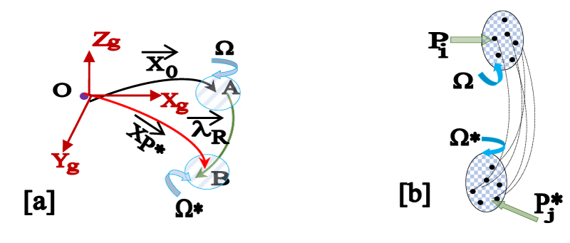
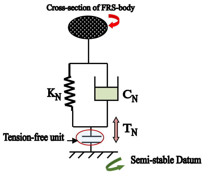
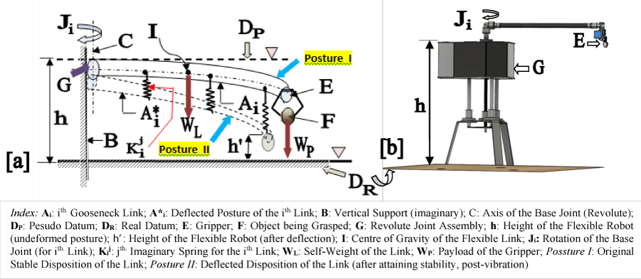
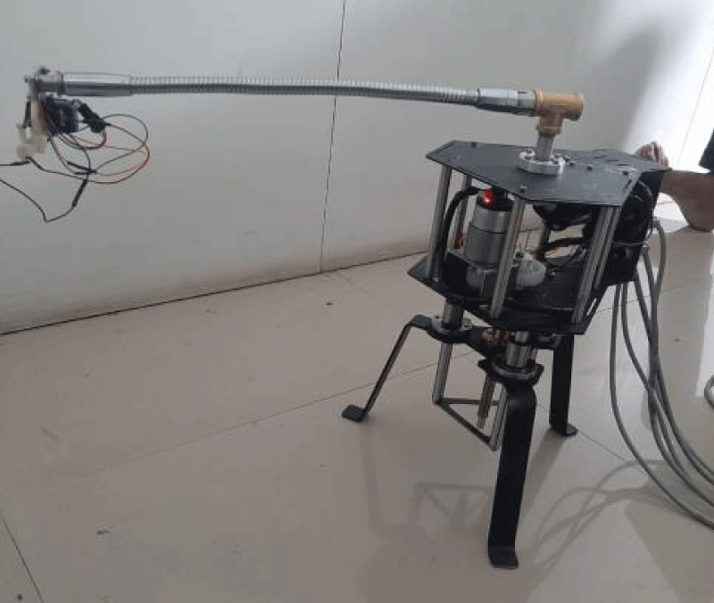
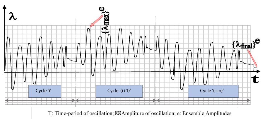
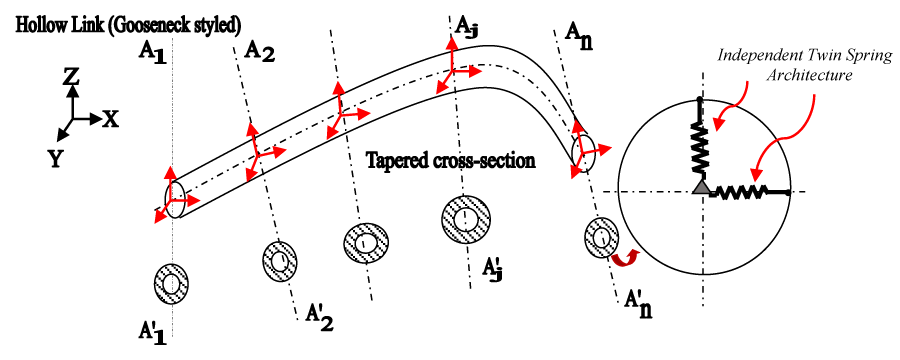
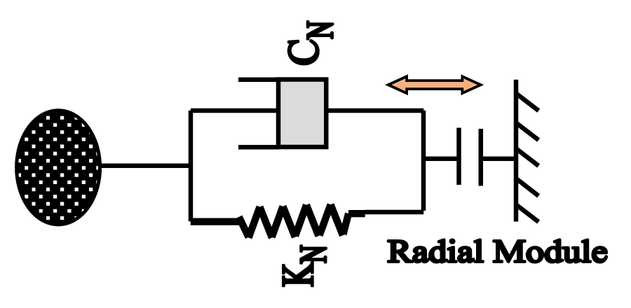

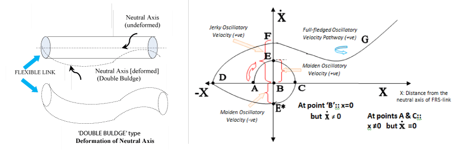
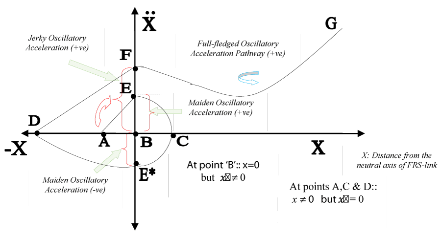
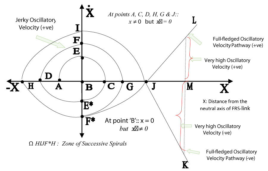
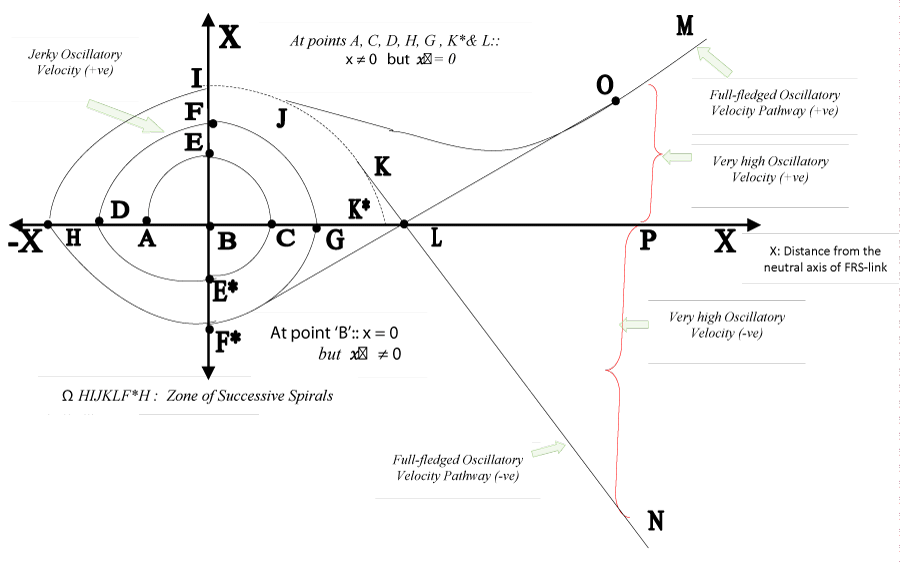
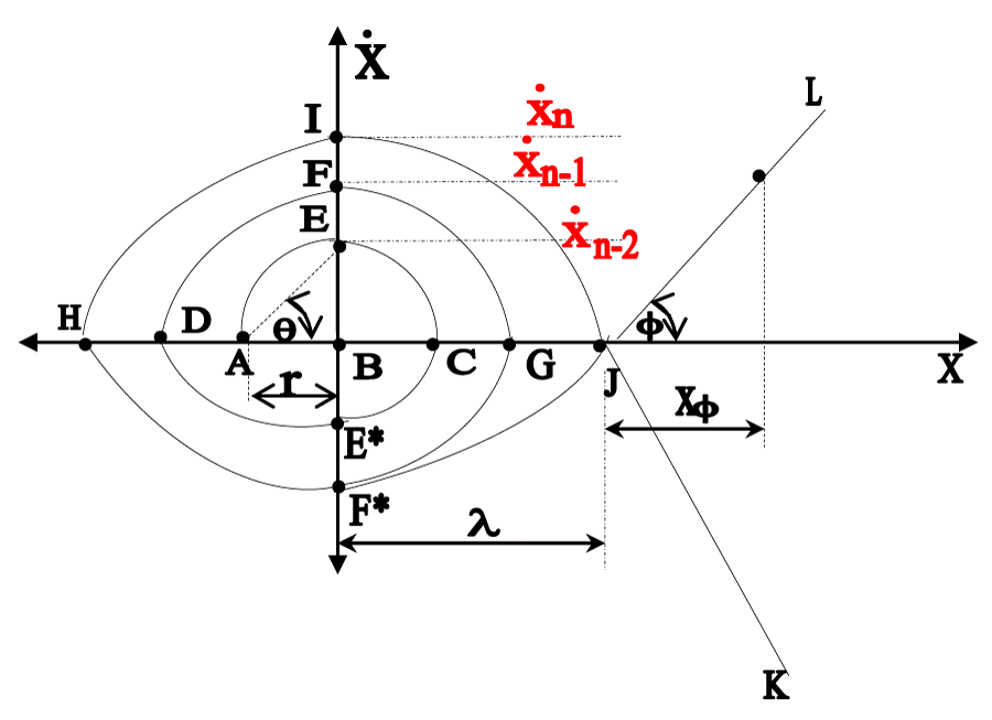
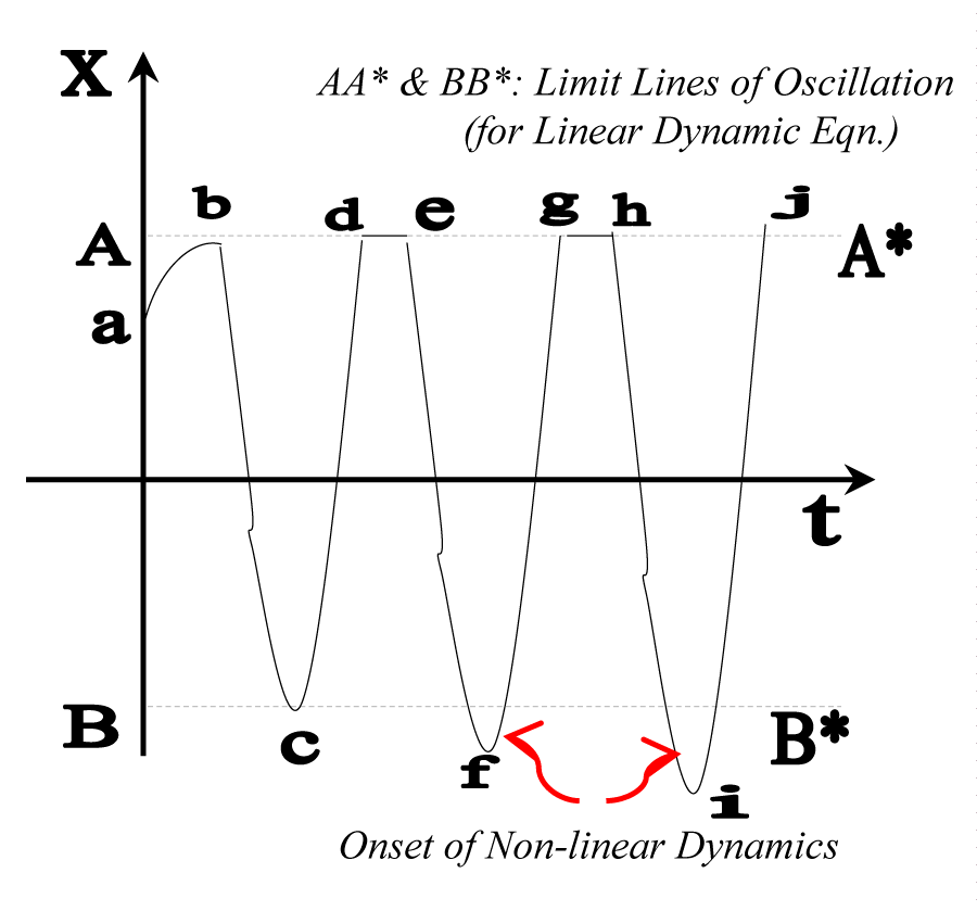
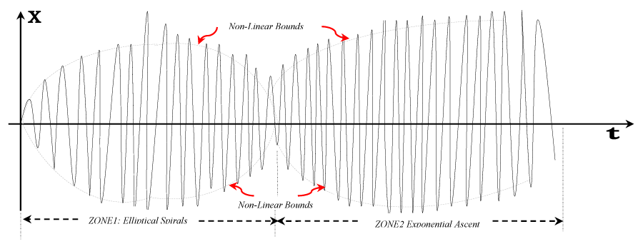

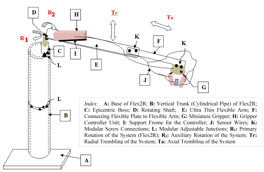
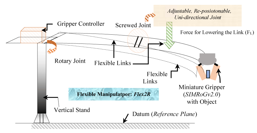
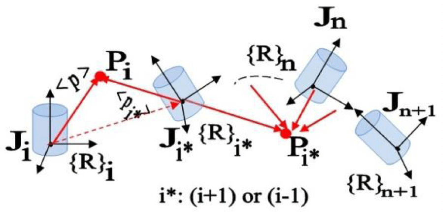
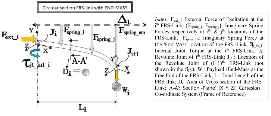

 Save to Mendeley
