Annals of Robotics and Automation
Modeling, Simulation and Proof-of-Concept of an Augmentation Ankle Exoskeleton with a Manually-Selected Variable Stiffness Mechanism
Shaikha F Abdulmajeed1, Khaled S Al-Kaabi2, Mohammad I Awad3,4*, Dongming Gan5 and Kinda Khalaf1,3
2R&D Department, Tawazon Technology and Innovation, Abu Dhabi, United Arab Emirates
3Health Engineering and Innovation Center, Khalifa University, Abu Dhabi, United Arab Emirates
4Khalifa University Center of Autonomous Robotic Systems, Khalifa University, Abu Dhabi, United Arab Emirates
5School of Engineering Technology, Purdue University West Lafayette, IN 47907, USA
Cite this as
Abdulmajeed SF, Al-Kaabi KS, Awad MI, Gan D, Khalaf K (2020) Modeling, Simulation and Proof-of-Concept of an Augmentation Ankle Exoskeleton with a Manually-Selected Variable Stiffness Mechanism. Ann Robot Automation 4(1): 013-017. DOI: 10.17352/ara.000004Despite its inherent complexity and wide dynamic variability, healthy human gait is distinguished by smoothness, stability and flexibility with minimal energy consumption. This is in part achieved by the human body’s superb inherent joint compliance. In particular, the ankle joint plays an important role with its continuous variable stiffness, as compared to the stiffness of the knee and hip joints which remain nearly constant during the loading phases of the gait cycle. This paper presents a proof-ofconcept of a bio-inspired unpowered-compliant ankle exoskeleton designed to assist in human walking and reduce the biological demands of the calf muscle. An unpowered variable stiffness mechanism was developed and integrated onto the ankle exoskeleton to harness gait energy and enhance the ankle’s biomechanical capabilities. The prototype was fabricated and validated on healthy subjects using preliminary experimental tests. The device uses a variable stiffness mechanism, which manually enables five levels of stiffness to replicate and compliment the human ankle’s range of motion. A slider is triggered by a passive mechanical clutch, which controls spring engagement. By engaging different levels on the slider, the system produces five different levels of stiffness in the range of 0.8-4.7 N.m.rad-1. The ankle exoskeleton presented here offers a promising opportunity to adjust ankle compliance and improve the robustness of walking by providing users with further adaptability.
Introduction
Human robot integration, particularly that focusing on human augmentation, is constantly evolving with significant advances achieved during the last decade promising to reshape the future of robotics. According to H. Herr, an exoskeleton is a mechanical device, essentially anthropomorphic in nature, worn by a user and operating in parallel to the human body [1]. An exoskeleton must operate in a manner compatible with human biomechanics without restricting the user’s movements.
Exoskeletons can function to augment human performance by increasing strength, endurance and other physical attributes needed to perform any type of activity. They could, for example, be utilized to lift heavy objects, carry objects over a long distance, or work with heavy machinery and tools. They can be used in confined spaces, such as warehouses, construction sites, or in specific contexts, such as disaster relief operations and military activities [2]. Uderstanding the performance of the human body during interaction with these exoskeletal systems is critical to these applications and insightful to further use in rehabilitation, physiology and biomechanics.
Augmentation exoskeletons are typically categorized based on the utilized actuation systems into actuated and passive exoskeletons. Actuated exoskeletons employ an actuation system (electrical, hydraulic, pneumatic, and hybrid) to exert torques and forces on the exoskeleton’s joints and links, thus enabling augmentation of task performance. Currently, there are a number of commercial augmentation exoskeletons and many more are under development. For example, BLEEX [3] and HULC [4], both employ hydraulic actuators. BLEEX uses an average walking speed of 1.3 m/s with a load of 34kg. The device however is sensitive to the forces and torques produced by the wearer [3]. The HULC has an approximate weight of 24kg, and was developed to reduce the vertical component of the weight carried by an individual. However, this device does not allow the production of torque to assist in the lifting or controlling of loads carried in the anterior-posterior (transverse plane) and medio-lateral (frontal plane) directions [4].
Electrically actuated devices include the HEXAR [5], which was developed for industrial use. This exoskeleton relies on two electric motors and works with muscle circumference sensors coupled to the user. Another example is the RB3D HERCULE [6], which allows transportation of loads up to 40 kg, and walking speeds of 5 km/hr. Lastly, the HAL-3 is a hybrid powered exo-suite designed by Cyberdyne [7]. It is used for rehabilitating patients with spinal cord injuries, as well as providing healthy users with strength augmentation. HAL-3’s unique feature lies in its ability to train patients to eventually perform movements independently without the need of wearing the exo-suite. This is mainly accomplished by sensors attached to the leg muscles, which detect electric signals sent from the brain to the muscles initiating and controlling movement. The exoskeleton then powers up and assists this motion, enhancing strength and stability by leveraging the patient’s nervous system to signal the robot [7].
Passive augmentation exoskeletons, unlike their actuated counterparts, do not utilize actuation systems to generate torques and forces. Instead, they use passive elastic elements to store and release energy during a designated phase in the gait cycle, hence allowing for the reduction of the metabolic consumption of muscles [8]. Collins, et al. [8] used a lightweight, low-power clutch to control spring engagement in an ankle exoskeleton. Based on electrostatic adhesion between thin electrode sheets coated with a dielectric material, they placed clutches in series with elastomer springs to allow control of spring engagement, in addition to several clutched springs placed in parallel to discretely adjust stiffness. By engaging different numbers of springs, their system produced six different levels of stiffness with forces ranging from 14 to 50 N.
Regarding ankle exoskeletons, the value of torsional stiffness plays a major role in impacting the system’s performance. This value is affected by many factors, including body mass, gait speed, and gait cycle frequency. Therefore, a variable stiffness mechanism capable of altering the stiffness of the ankle exoskeleton joint to meet various physiological task demands, is key to successful adaptive performance. Several concepts have been proposed in literature. These include the unpowered exoskeleton proposed in [8], which utilizes an unpowered ratchet mechanism to control an elastic element placed in parallel to the user’s leg. In [9], Electrostatic adhesion clutches are placed in series with springs for control, while clutched springs are placed in parallel to adjust the stiffness of the ankle [10]. Developed a low-profile unpowered ankle exoskeleton to reduce the calf’s muscle expenditure, while [11], prototyped a passive ankle exoskeleton with artificial tendon and [12], built a a passive leg exoskeleton that reduces metabolic consumption through hopping.
In this paper, we present the proof-of-concept of a passive ankle exoskeleton with a discrete-variablestiffness mechanism. The system utilizes a lever mechanism with discrete lever arm lengths. The lever arm mechanism and the discrete variable stiffness actuators have been used in our previous passive exoskeleton design [13-15]. The paper is organized as follows: In section 2, the concept and the modeling of the variable stiffness mechanism is proposed. Section 3 details the simulation and the experimental validation for the proposed model, while in section 4, the discussion conclusions, and future directions are presented.
Methodology
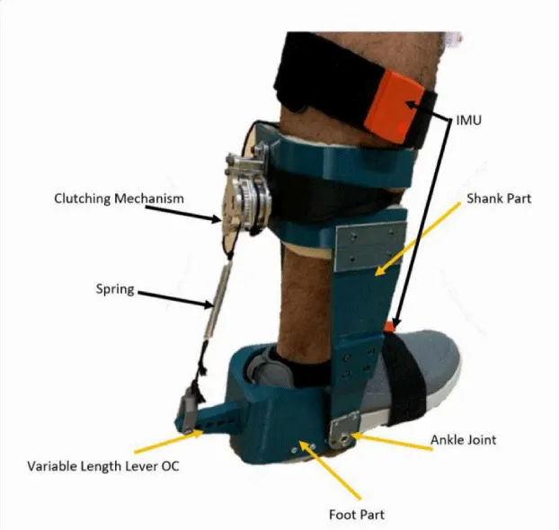
The design of the proposed augmentation ankle exoskeleton is shown in Figure 1. The design utilizes the clutching mechanism proposed in [8]. This mechanism is responsible for the engagement and disengagement of the spring in the gait cycle. As explained in [8], from 0-20% of the gait cycle, the clutching mechanism would be in the ratcheting stage where the spring would be held at its free length to enable it to stretch along 20-50% of the gait cycle. Once the foot leaves the ground, the clutching mechanism is released yielding to spring’s recoil [8].
Concept, physical model and simulation
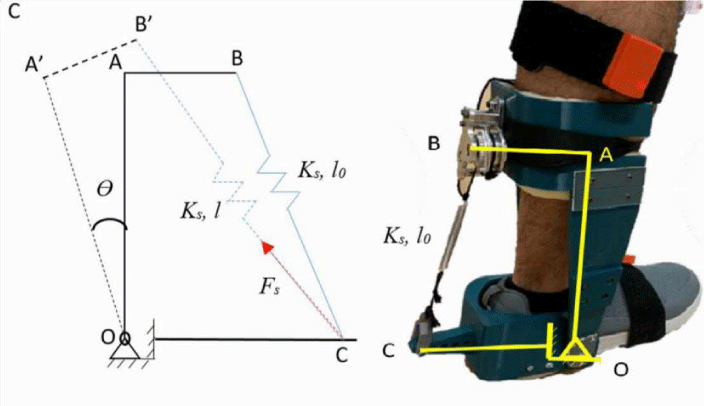
As mentioned before, the spring is only effective when the clutching mechanism is engaged. The variable stiffness mechanism developed here is inspired by the semi-active variable stiffness used in car-suspension systems [16]. The schematic of the mechanism is illustrated in Figure 2. The lever arm OA, is pinned at a fixed point ‘O’, around which it is free to rotate The spring BC is pinned to the lever arm at point ‘B’ and is free to rotate around ‘B’, while ‘C’ is free to translate along the cantilever arm OC. The lever arm OA is rotated around point ‘O’ through the ankle joint angle ‘θ’, which creates a force ‘Fs’ by the spring BC acting on the lever arm OA. The overall stiffness of the system is varied through the displacement of point ‘B’ on the lever arm OA. The variable ‘k’ represents the spring constant, while the variable ‘0’ represents the free length of the spring BC while it is at rest. The angle ‘θ’ is controlled by ankle movement in the sagittal plane, thus creating a displacement on the spring, which in turn produces the force ‘F’ exerted on point ‘C’. This force on point ‘C’ creates a torque on point ‘O’ through the lever arm OC.
To derive the ankle stiffness model as a function of the ankle’s angular displacement (θ), the kinematics of the system are formulated by defining the relation between the vectors:
When the structure OAB rotates around point O with an angular displacement of ‘θ’, vectors are represented as follows:
The Spring Force (Fs) is defined based on Hook’s law:
Where
From equations 1-7, it can be noted that the force Fs is a function of θ. Therefore, to calculate the torque around point O:
The torsional stiffness of the mechanism (Kexo) can be presented by:
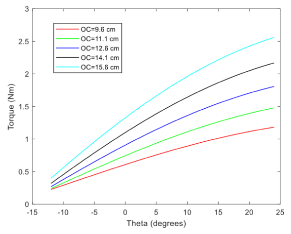
The model was simulated using MATLAB (The MathWorks Inc., USA). Figure 2 depicts the relationship between the torque generated around the ankle joint (point O) and the angular deflection of the ankle. According to [8], the angular position of the ankle joint ranges from -12 degrees to 24 degrees. It can be seen from the Figure that the torque increases with increased lever length ( ).
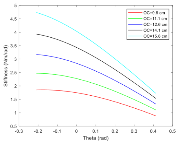
Accordingly, the exoskeleton’s ankle stiffness is higher for higher values of ( ) (Figure 3). The relationship between the stiffness and the angular deflection of the ankle is illustrated in Figure 4, where The level of stiffness decreases with an increase in angular deflection. This can be related to the behavior of the torque function, for which the slope decreases at higher angular positions.
Design, realization and preliminary validation
The exoskeleton prototype is presented in Figure 1, inspired by the design detailed in [8]. The structure of the exoskeleton was 3D printed using Acrylonitrile Butadiene Styrene (ABS) material. The lowest segment (emulating the foot) is mounted on the user’s shoes using screws. The variable length lever ( ). is embedded within the foot part of the exoskeleton. The upper part of the exoskeleton (emulating the shank) includes the clutching mechanism. The clutching mechanism used here is based on [8]. The spring is attached between the clutching mechanism and the fixed lever. The value of the spring has been selected from off-shelf hook springs according to [8]. The specific parameters of the fabricated exoskeleton are presented in Table 1.
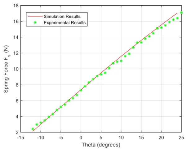
In order to validate the simulation results, an experimental setup has been devised. A force/torque sensor (ATI Mini) is attached between the variable stiffness lever and spring cable to measure the spring force (Fs) in both magnitude and direction. A quadrature encoder (E6C2-CWZ3E) is mounted on ankle joint to measure the ankle angular position (θ). Those sensors were connected to A National Instrument DAQ (NI-USB-6343) and the National Instrument LabVIEW® were used for data acquisition at 1000 Hz. As this is preliminary study, only the third level (‖( ). ‖=12.6 cm) was tested. The results are shown in Figure 5. It can be seen that the experimental results matches the simulation results for the spring force magnitude (Fs) with the ankle deflection (θ).
Conclusions and limitations
This paper presented the development and preliminary validation of an augmentation ankle exoskeleton with a manually controlled variable stiffness mechanism inspired by the lever method of stiffness alteration. System kinematic and kinetic models were illustrated and simulated. The exoskeleton was realized through 3D printing using ABS. A preliminary experimental setup was devised to validate the simulation results.
It should be noted, however, that the current realized exoskeleton merely serves as proof-of-concept to verify the feasibility of realizing a light weight, variable stiffness exoskeleton with minimal power consumption. Further work is warranted to improve design and validation. Although the current system is unpowered due to the manual selection of the stiffness levels, several improvements should be implemented. For example, replacing the manual selection method with a linear actuator would facilitate altering the stiffness during operation towards enhancing the efficiency of the exoskeleton. Moreover, the prototype can be improved using a better material in terms of strength and toughness in order to increase the lifespan and robustness of the exoskeleton. The thickness of the ankle brace could also be substantially reduced and positioned closer to the biological ankle joint to further reduce any lost energy. Further investigation regarding experimental testing on users to quantify the reduction in metabolic energy consumption of the muscles is underway.
- Herr H (2009) Exoskeletons and orthoses: classification, design challenges and future directions. Journal of NeuroEngineering and Rehabilitation 6: 21. Link: https://bit.ly/33Iczsg
- Narayan R (2018) Encyclopedia of Biomedical Engineer: Exoskeletons. 1st edition. Link: https://bit.ly/2XN4teh
- Zoss AB, Kazerooni H, Chu A (2006) Biomechanical design of the Berkeley lower extremity exoskeleton (BLEEX). In IEEE/ASME Transactions on Mechatronics 11: 128-138. Link: https://bit.ly/3gMffbW
- Link: https://bit.ly/33K4V0s
- Kim W, Lee H, Kim D (2014) Mechanical design of the Hanyang Exoskeleton Assistive Robot (HEXAR). International Conference on Control, Automation and Systems (ICCAS) 479-484. Link: https://bit.ly/2XFek5N
- RB3D. Hercule V3. Link: https://bit.ly/3iqwz70
- Oliver J, Grasmuecke D, Meindl R, Tegenthoff M, Schwenkreis P, et al. (2017) Hybrid assistive limb exoskeleton HAL® in the rehabilitation of chronic SCI: Proof of concept, the results of 21 patients. World Neurosurg 110: e73-e78. Link: https://bit.ly/3fKjgMW
- Collins SH, Wiggin MB, Sawicki GS (2015) Reducing the energy cost of human walking using an unpowered exoskeleton. Nature 522: 212-215. Link: https://go.nature.com/3gWiA8J
- Diller S, Majidi C, Collins SH (2016) A lightweight, low-power electroadhesive clutch and spring for exoskeleton actuation. 2016 IEEE International Conference on Robotics and Automation (ICRA), Stockholm 682-689. Link: https://bit.ly/3a9V5WW
- Yandell MB, Tacca JR, Zelik KE (2019) Design of a Low Profile, Unpowered Ankle Exoskeleton That Fits Under Clothes: Overcoming Practical Barriers to Widespread Societal Adoption. IEEE Trans Neural Syst Rehabil Eng 27: 712-723. Link: https://bit.ly/3irbs4w
- van Dijk W, van der Kooij H, Hekman E (2011) A passive exoskeleton with artificial tendons: Design and experimental evaluation. 2011 IEEE International Conference on Rehabilitation Robotics, Zurich 1-6. Link: https://bit.ly/2PG7DvG
- Link: https://bit.ly/30HIpU3
- Awad MI, Gan D, Cempini M, Cortese M, Vitiello N, et al. (2016) Modeling, design & characterization of a novel Passive Variable Stiffness Joint (pVSJ)," 2016 IEEE/RSJ International Conference on Intelligent Robots and Systems (IROS), Daejeon 323-329. Link: https://bit.ly/33JiJIM
- Awad MI, Gan D, Az-Zu'bi A, Dias JM, Thattamparambil J, et al. (2016) Novel passive Discrete Variable Stiffness Joint (pDVSJ): Modeling, design, and characterization. 2016 IEEE International Conference on Robotics and Biomimetics (ROBIO), Qingdao, 1808-1813. Link: https://bit.ly/3a8w8v8
- Awad MI, Hussain I, Gan D, Az-Zu'bi A, Dias JM, et al. (2019) Passive Discrete Variable Stiffness Joint (pDVSJ-II): modeling, design, characterization, and testing toward passive haptic interface. Journal of Mechanisms and Robotics 11. Link: https://bit.ly/3gK1x9I
- Anubi MO, Crane C (2015) A New Semiactive Variable Stiffness Suspension System Using Combined Skyhook and Nonlinear Energy Sink-Based Controllers. IEEE Transactions On Control Systems Technology 23: 937-947. Link: https://bit.ly/31EngcP

Article Alerts
Subscribe to our articles alerts and stay tuned.
 This work is licensed under a Creative Commons Attribution 4.0 International License.
 Save to Mendeley
